
Underwater Vehicles and Inspection Methods

a technology for underwater infrastructure and vehicles, applied in underwater equipment, special-purpose vessels, passenger handling apparatus, etc., can solve the problems of difficult access to shallow water sites, difficult inspection of underwater infrastructure, and less than or equal to 10 m depth, etc., and achieve the effect of improving the monitoring of inspection sensors

Inactive Publication Date: 2018-03-22
SAUDI ARABIAN OIL CO
View PDF3 Cites 23 Cited by
  • Summary
  • Abstract
  • Description
  • Claims
  • Application Information

AI Technical Summary

Benefits of technology

The patent describes a subsea robot that can inspect and inspect underwater equipment. The robot has a positioning system that uses treads to minimize damage to the underwater environment. The robot also has a camera to help gather better visual information. These features make it easier to inspect and repair underwater equipment in a safe and efficient way.

Problems solved by technology

Inspection of underwater infrastructure, especially in shallow water environments, can be difficult.
Shallow water sites (e.g., anything less than or equal to 10 m depth) are difficult to access with sophisticated Diving Support Vessels (DSVs) that are typically used for inspecting underwater pipelines in deeper water with help of tethered divers and / or remotely operated vehicles (ROVs').
Shallow water environments limit the ability of support vehicles to navigate in close proximity to the structures being inspected.
The separation between the support vehicle causes a number of problems with operation of the vehicle, including issues of communication and control over a distance, the need for the robot to travel a distance from the support vehicle to the structure to be inspected, and the ability of the robot to perform inspection and other tasks once the robot is in position.

Method used


Image

  • Underwater Vehicles and Inspection Methods
  • Underwater Vehicles and Inspection Methods
  • Underwater Vehicles and Inspection Methods

Examples


Embodiment Construction

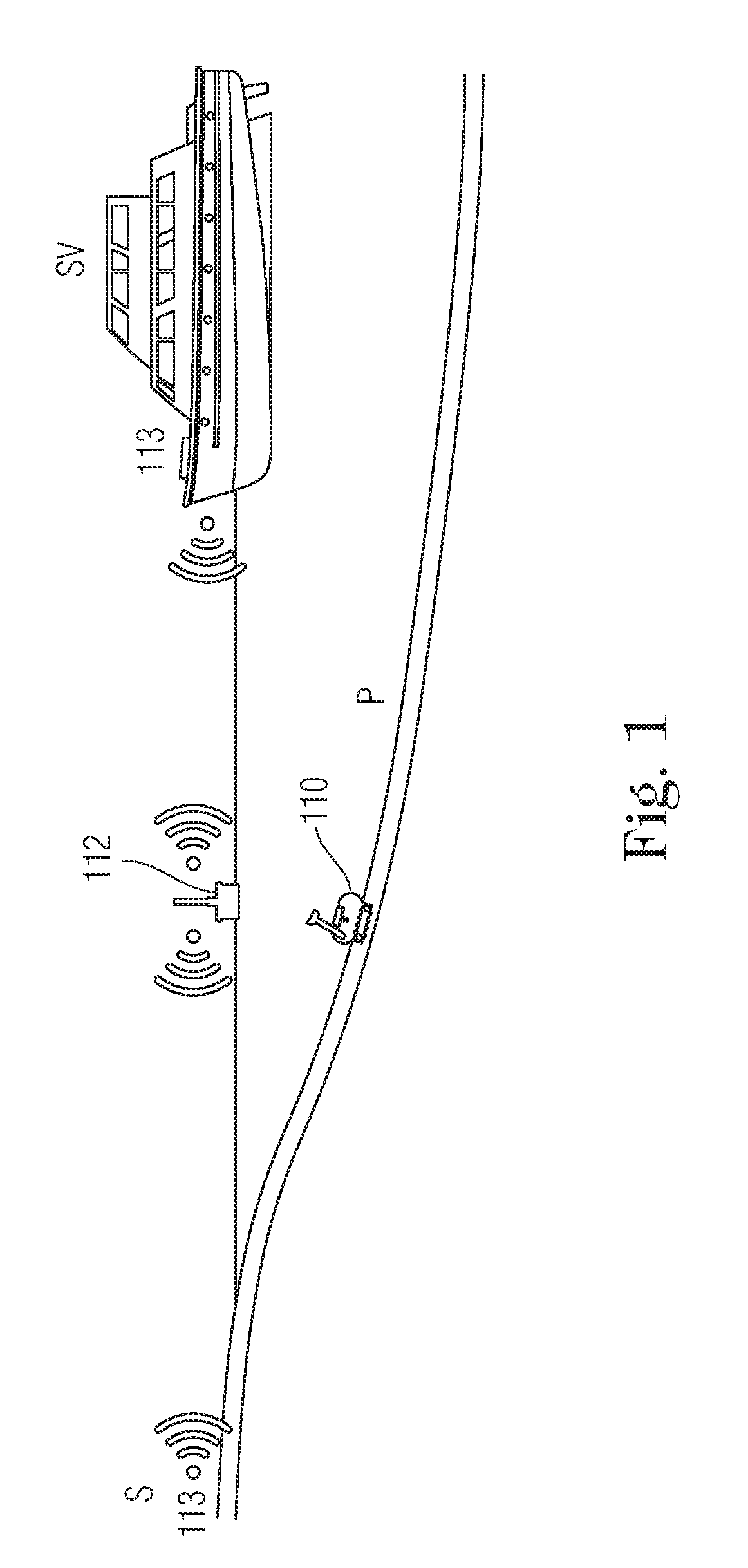
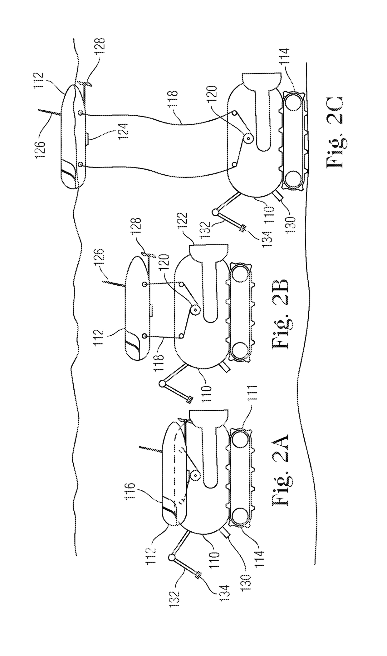
[0039]Referring to FIG. 1, an aquatic environment robotic system 100 is shown. A pipeline P is an example of target infrastructure that is to be operated upon by an underwater robotic vehicle 110. The section of the pipeline P to be operated upon is located in shallow water. A support vessel SV is located near the section of the pipeline P that is to be operated upon, but is prevented from being positioned directly over the area to be inspected because of the shallow depth of the water. Accordingly, the support vessel SV is located in deeper water a distance from the target area of the pipeline. The underwater robotic vehicle can be launched from the SV and travel to the area of the pipe to be inspected. Alternatively, the underwater robotic vehicle 110 can be deployed from the shore S and move through the water to arrive at the area of the pipe P to be inspected. As such, a control station 113 can be located on the support vessel SV and / or shore S and can depend on whether the unde...


PUM


Abstract

A method for performing operations using a water environment robotic system on a target section of pipeline located in an underwater environment is provided. The method includes the steps of deploying the underwater robotic vehicle into the water and visually inspecting the underwater environment to locate the pipeline and its plurality of weld joints. A cleaning operation is performed at one of the plurality of weld joints using the underwater robotic vehicle. The robotic vehicle can land on the sea floor and deploy a robotic arm to inspect the cleaned weld joint. The underwater can then swim to a next weld joint and land and perform cleaning and inspection operations, which can be repeated until all inspection sites are inspected.

Description

CROSS-REFERENCE TO RELATED APPLICATIONS[0001]This application claims priority under 35 U.S.C. § 119 to U.S. Provisional Application Ser. No. 62 / 396,937, filed Sep. 20, 2016, which is hereby incorporated by reference as if set forth in its entirety herein.FIELD OF THE INVENTION[0002]A system, method, and devices for performing underwater tasks that includes an underwater robot and reusable buoyancy modules.BACKGROUND OF THE INVENTION[0003]Inspection of underwater infrastructure, especially in shallow water environments, can be difficult. Shallow water sites (e.g., anything less than or equal to 10 m depth) are difficult to access with sophisticated Diving Support Vessels (DSVs) that are typically used for inspecting underwater pipelines in deeper water with help of tethered divers and / or remotely operated vehicles (ROVs'). Generally, these vessels have a dynamic positioning (DP) system that enables them to stabilize in specific position above the intended targeted inspection sites. A...

Claims


Application Information

Patent Timeline
IPC IPC(8): B63G8/14B63B27/00B63B59/08B63G8/00B63G8/39G01N29/04G01N29/24B08B9/023
CPCB63G8/14B63B27/00B63B59/08B63G8/001B63G8/39G01N29/041G01N29/245B08B9/023B63G2008/005F16L55/00G01N2291/0234G01N2291/267G01N29/225G01N29/265F16L1/265B63C11/52
Inventor ABDELLATIF, FADLOUTA, ALIPATEL, SAHEJADAMER, AYMANTRIGUI, HASSANE
Owner SAUDI ARABIAN OIL CO
Learn More