
Soc supply droop compensation

a technology of supply voltage and compensation, applied in pulse manipulation, pulse technique, instruments, etc., can solve the problems of slow operation of integrated circuitry, voltage supply may decrease, and difficulty in providing stable power to circuitry, so as to prevent supply voltage droop, prevent logic failure, and increase clock delay

Active Publication Date: 2018-03-01
ENDURA IP HLDG LTD
View PDF2 Cites 0 Cited by
  • Summary
  • Abstract
  • Description
  • Claims
  • Application Information

AI Technical Summary

Benefits of technology

This patent is about preventing logic failures in computer chips by addressing supply voltage droop and clock delay. Supply droop is when the power supply to the chip decreases, causing performance issues. Clock stretching is a technique that helps prevent this by temporarily extending the timing of the clock signals used by the chip's logic circuitry. This reduces the current demand and thus the droop amplitude. This technique can also be used to control clock pulse skipping, which can cause performance throttling, or to maintain performance in the face of large voltage ripple and performance throttling. Overall, this patent offers a solution for improving the reliability and performance of computer chips.

Problems solved by technology

The changes in utilized power may present difficulties in providing stable power to the circuitry, and voltage supplied may decrease, or droop, when power regulation circuits are faced with rapid increases in power demands.
These voltage droops may result in slower operation of integrated circuitry, and may result in combinatorial logic failures, particularly for system on chip (SoC) devices, in which voltage droops may not be uniform over the device.
In other words, temporary mismatch between load current and voltage regulator current delivery leads to power supply droop.
The effect of supply droops in SoC is to lead to failure in sampled combinational paths.
Supply droops increase the delay in logic paths.

Method used


Image

  • Soc supply droop compensation
  • Soc supply droop compensation
  • Soc supply droop compensation

Examples


Embodiment Construction

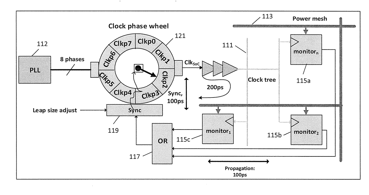
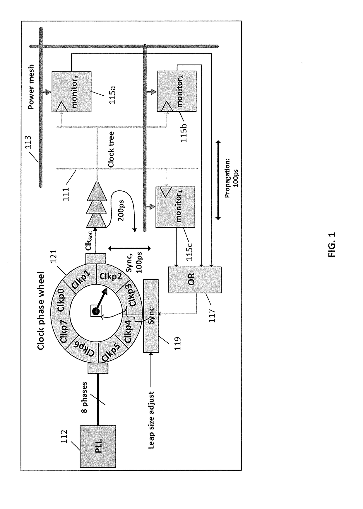
[0027]Some embodiments in accordance with aspects of the invention include a plurality of droop monitors within an integrated circuit, the droop monitors configured to detect occurrence of a droop in voltage level below a specified level of a regulated supply voltage, and clock adjustment circuitry configured to stretch a period of a clock signal supplied to portions of the integrated circuit in response to detection of the occurrence of the droop in voltage level below the specified level.

[0028]In some embodiments the droop monitors monitor a speed of execution of sensing integrated circuitry compared to speed of execution of reference integrated circuitry. In some embodiments the sensing integrated circuitry and the reference integrated circuitry each comprise a delay line. In some embodiments the reference integrated circuitry is provided power at a first voltage level and the sensing integrated circuitry is provided power at the regulated supply voltage level.

[0029]In some embod...


PUM


Abstract

Droop monitors spread across a system-on-chip (SoC) monitor for voltage droops in regulated supply voltage supplied to logic circuitry of the SoC. In the event of a voltage droop, a clock signal supplied to the logic circuitry is stretched, to temporarily increase a period of the clock signal. The droop monitors may include a sensing delay line provided voltage at the regulated supply voltage, and a reference delay line supplied with a reference voltage, with operations of the delay lines monitored to determine a voltage droop.

Description

CROSS REFERENCE TO RELATED APPLICATION[0001]This application claims the benefit of the filing date of U.S. Provisional Patent Application No. 62 / 357,852, filed on Jul. 1, 2016, the disclosure of which is incorporated by reference herein.BACKGROUND OF THE INVENTION[0002]The present invention relates generally to supply of power to integrated circuits, and more particularly to detecting and / or compensating for power supply droops to integrated circuits.[0003]Integrated circuits may be largely quiescent at times, drawing little power, while at other times may in whole or in part require large amounts of power. The changes in utilized power may present difficulties in providing stable power to the circuitry, and voltage supplied may decrease, or droop, when power regulation circuits are faced with rapid increases in power demands. These voltage droops may result in slower operation of integrated circuitry, and may result in combinatorial logic failures, particularly for system on chip (...

Claims


Application Information

Patent Timeline
Patent Type & Authority Applications(United States)
IPC IPC(8): H03K5/15H03L7/089G05F3/08H02M3/155
CPCH03K5/15H03L7/0891G05F3/08H02M3/155H03K2005/00019G01R19/16552G01R19/165G05F1/565H03K5/1252
Inventor IHS, HASSAN
Owner ENDURA IP HLDG LTD
Learn More