Steering control device

Active Publication Date: 2018-03-01
JTEKT CORP +2
View PDF2 Cites 2 Cited by
  • Summary
  • Abstract
  • Description
  • Claims
  • Application Information

AI Technical Summary

Benefits of technology

The patent is about a device that helps control the steering of a vehicle. The device suppresses a problem where the motor current may fluctuate too much when the vehicle reaches the end of its travel. To address this issue, the device gradually decreases the amount of correction applied to the motor current to ensure a smooth change in the command value set by the device's controller. This results in a smoother and more accurate control of the vehicle's steering.

Problems solved by technology

Accordingly, in the case where the current value of the surplus current waveform, which is stored in advance, is sequentially subtracted as in the above control device, the current flowing through the motor may be excessively decreased or may be excessively increased depending on the changing rate of the turning angle at the time when the end abutment occurs.
When the current flowing through the motor is excessively decreased, actual torque of the motor becomes insufficient as compared to an appropriate magnitude of the torque for maintaining the turning angle at the limit angle.
As a result, the steering wheel is returned in a reverse direction, and thus, a user may feel a sense of discomfort.
When the current flowing through the motor is excessively larger than the appropriate current, the torque of the motor is excessively increased, and thus, a load is applied to a steering system.
As a result, the output value of the integral element tends to become excessively larger than an appropriate value for controlling the current flowing through the motor to the current command value.

Method used


Image

  • Steering control device
  • Steering control device
  • Steering control device

Examples


Embodiment Construction

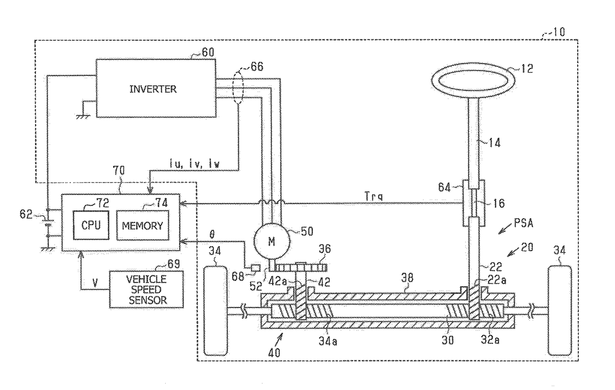
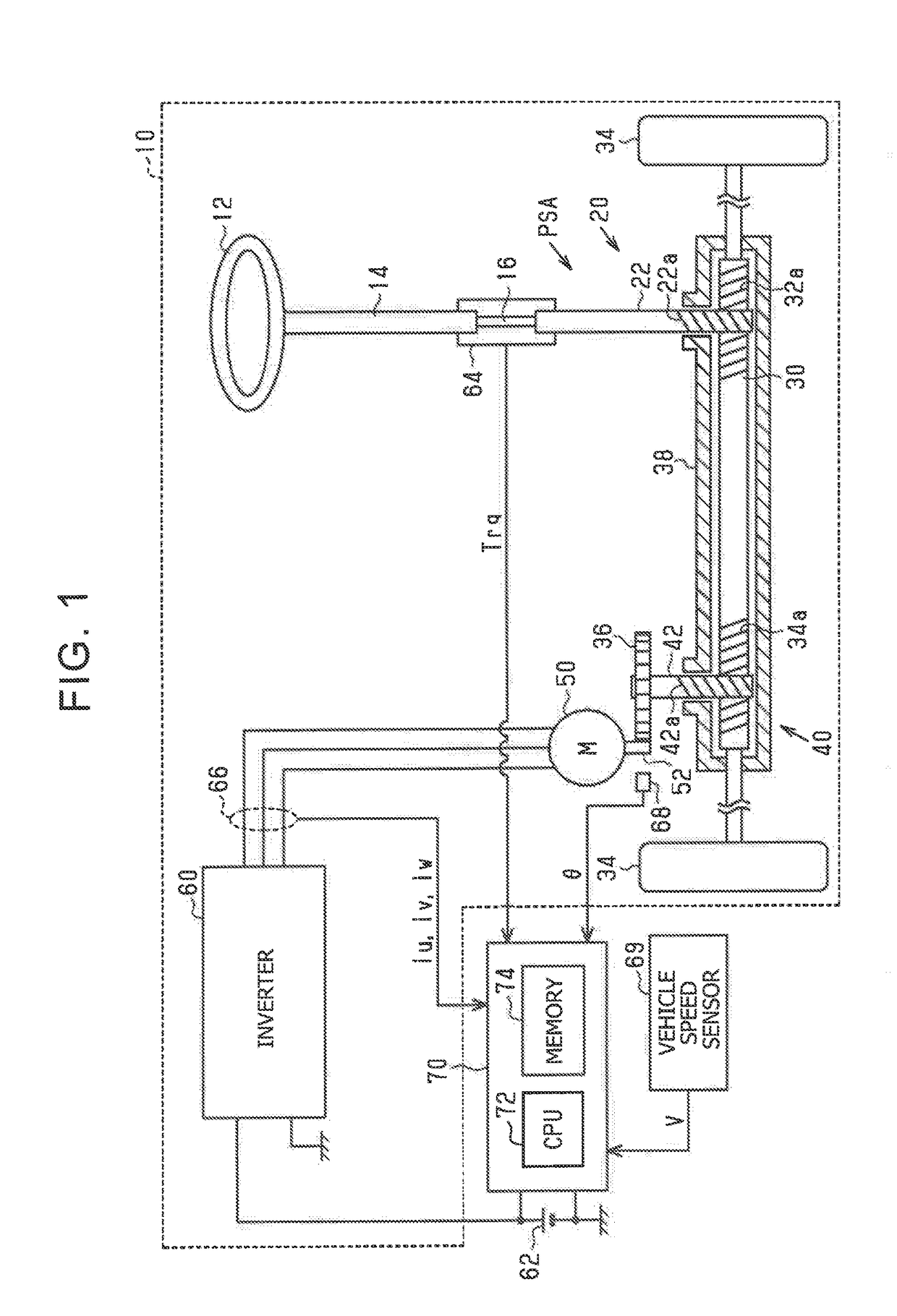
[0020]A steering control device according to an embodiment of the disclosure will be described with reference to the drawings. As shown in FIG. 1, in a steering system 10 according to the embodiment, a steering wheel 12 can be coupled to a pinion shaft 22 of a turning actuator PSA via a steering shaft 14. The turning actuator PSA includes a first rack and pinion mechanism 20, a second rack and pinion mechanism 40, a surface permanent magnet synchronous motor (SPM) (hereinafter, may be referred to as “motor 50”), and an inverter 60.

[0021]The first rack and pinion mechanism 20 includes a rack shaft 30 and the pinion shaft 22 that are arranged at a specified crossing angle, and first rack teeth 32a formed on the rack shaft 30 mesh with pinion teeth 22a formed on the pinion shaft 22. Note that steered wheels 34 are respectively coupled to both ends of the rack shaft 30 via tie rods.

[0022]The second rack and pinion mechanism 40 includes the rack shaft 30 and a pinion shaft 42 that are ar...


PUM


Abstract

A steering control device includes a command value setting processing portion configured to set a current command value based on a detection value of steering torque; a feedback processing portion configured to control a voltage applied to a motor so as to control a current flowing through the motor to the current command value, based on an output value of an integral element obtained by using a difference between the current and the current command value; an end determination processing portion configured to determine whether a turning angle of steered wheels has reached a limit angle; and an end-time limit processing portion configured to perform correction to increase a magnitude of the difference, based on a degree of a decrease in a magnitude of a rotational speed of the motor when the end determination processing portion determines that the turning angle has reached the limit angle.

Description

INCORPORATION BY REFERENCE[0001]The disclosure of Japanese Patent Application No. 2016-165885 filed on Aug. 26, 2016 including the specification, drawings and abstract is incorporated herein by reference in its entirety.BACKGROUND1. Technical Field[0002]The disclosure relates to a steering control device configured to control a steering system, the steering system including a turning actuator that turns steered wheels of a vehicle, and the steering system assisting turning of the steered wheels in accordance with steering of a steering wheel.2. Description of Related Art[0003]For example, in Japanese Patent Application Publication No. 2009-143312 (JP 2009-143312 A), a steering control device is described. The steering control device executes control that reduces an impact that is generated at a time when a steering angle of a steering wheel reaches a specified amount, which leads to so-called end abutment, and thus, a turning angle of steered wheels reaches a limit angle. The contro...

Claims


Application Information

Patent Timeline
IPC IPC(8): B62D6/00B62D5/04B62D5/00G01L5/22G01P1/02
CPCB62D6/008B62D5/0463B62D5/006H02P21/0003G01P1/026B62D3/12H02P27/06G01L5/221H02P21/22B62D5/046B62D5/0469H02P21/18
Inventor TOKO, TAKAHIROTAMAKI, HIROMASAHASEGAWA, JUNFUJITA, SHOHEIYANAI, KOHEISUZUKI, TATSUYAMIYAKE, TATSUYASUZUKI, TAKASHI
Owner JTEKT CORP
Why Eureka
Try Eureka