Lighting device and illumination apparatus using the same
- Summary
- Abstract
- Description
- Claims
- Application Information
AI Technical Summary
Benefits of technology
Problems solved by technology
Method used
Image
Examples
first embodiment
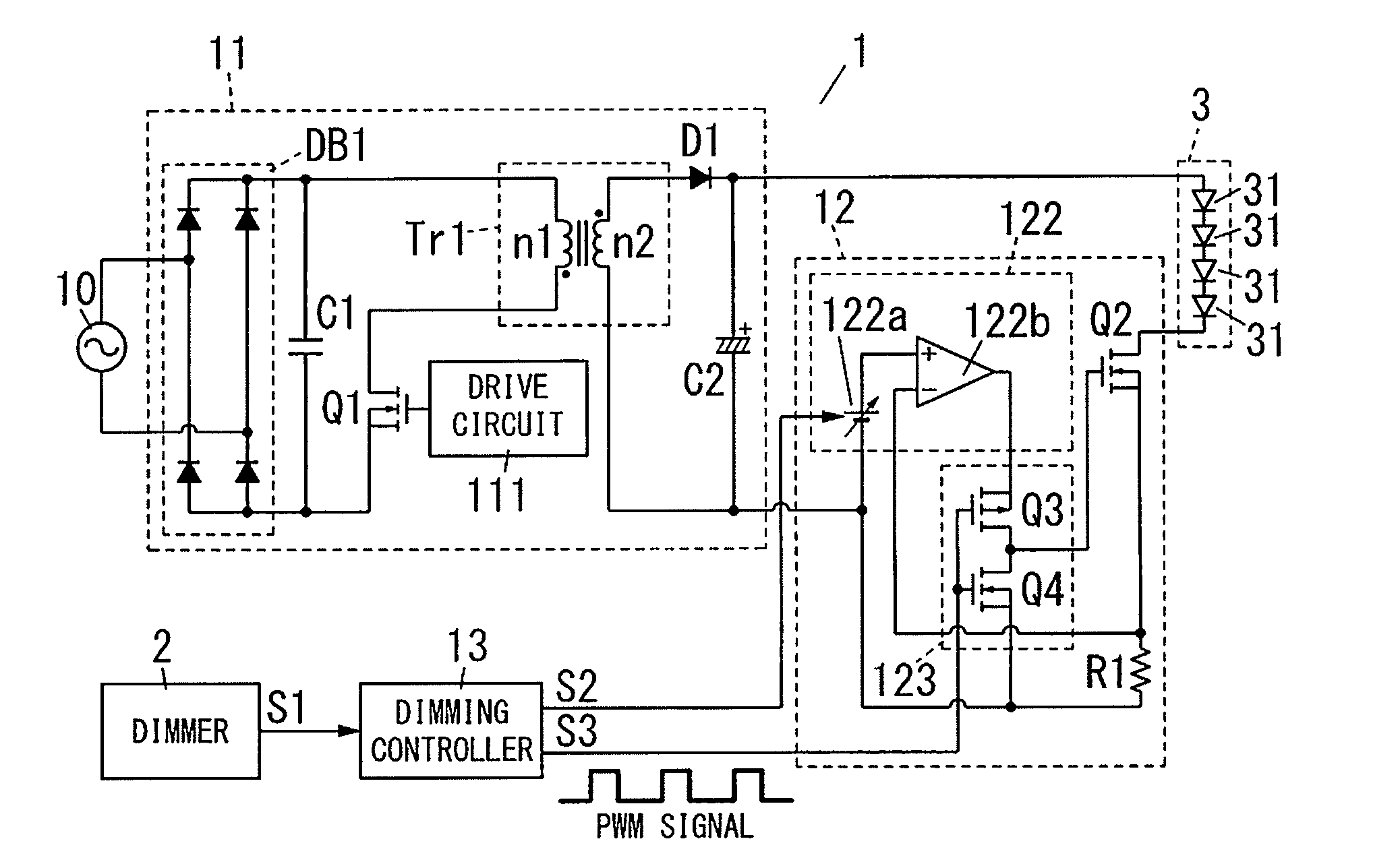
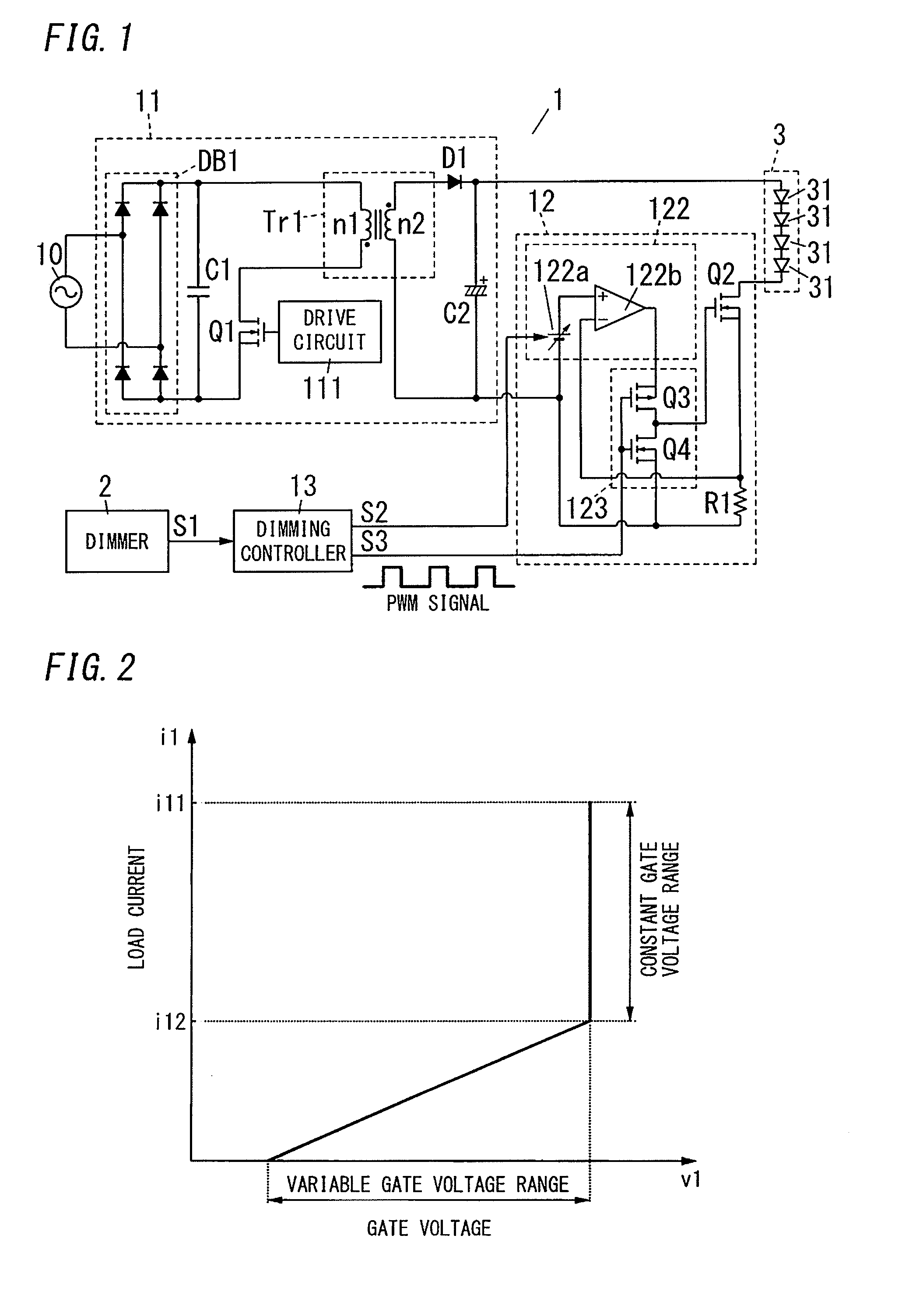
[0028]FIG. 1 is a circuit diagram illustrating one example of a lighting device 1 according to the present embodiment. This lighting device 1 includes a DC power supply 11, a current-adjusting part 12, and a dimming controller 13. The lighting device 1 is configured to light a light-emitting part 3 at a luminous level according to a dimming signal S1 (dimming instruction signal) that is output from a dimmer 2.
[0029]The light-emitting part 3 includes a plurality of LEDs 31 (light emitting elements) that are connected in series (four LEDs in FIG. 1). The light-emitting part 3 is connected across output ends of the DC power supply 11, via a transistor Q2 (switching element) and a resistor R1. The number of the LEDs 31 constituting the light-emitting part 3 may be one, two, three, five or more. The light-emitting part 3 may be constituted by the LEDs 31 connected in parallel.
[0030]The DC power supply 11 is connected to an AC power source 10, and is configured to convert, into a DC volta...
second embodiment
[0055]A lighting device 1 according to the present embodiment will be described with reference to FIGS. 6 to 8. Because circuit configuration of the lighting device 1 is similar to that of the First Embodiment, explanation thereof will be basically omitted here and described with reference to FIG. 1 if necessary.
[0056]As shown in FIG. 1, the lighting device 1 according to the present embodiment includes a DC power supply 11, a current-adjusting part 12 and a dimming controller 13. The lighting device 1 is configured to light a light-emitting part 3 at a luminous level according to a dimming signal S1 that is output from a dimmer 2.
[0057]Next, operation of the lighting device 1 will be described with reference to FIGS. 6 to 8.
[0058]FIG. 6 is a graph illustrating a relationship between a gate voltage v1 of a transistor Q2 in the current-adjusting part 12 and a load current i1 flowing through the light-emitting part 3. From this graph, it can be seen that the gate voltage v1 is reduced...
third embodiment
[0071]A lighting device 1 according to the present embodiment will be described with reference to FIGS. 9 and 10. Because circuit configuration of the lighting device 1 is similar to that of the First Embodiment, explanation thereof will be basically omitted here and described with reference to FIG. 1 if necessary.
[0072]As shown in FIG. 1, the lighting device 1 according to the present embodiment includes a DC power supply 11, a current-adjusting part 12 and a dimming controller 13. The lighting device 1 is configured to light a light-emitting part 3 at a luminous level according to a dimming signal S1 that is output from a dimmer 2.
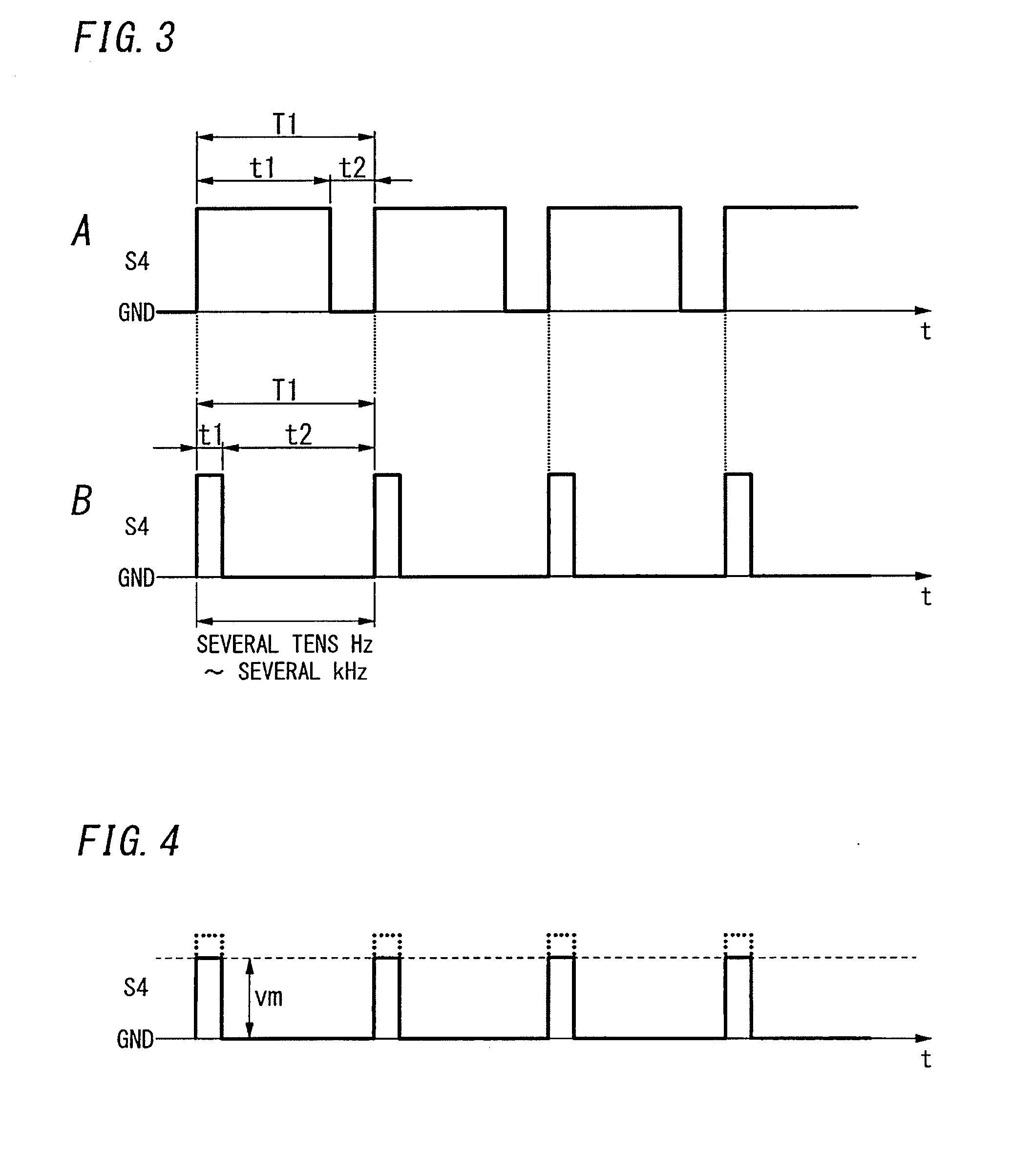
[0073]Each of A and B in FIG. 9 shows a gate signal S4 sent to a transistor Q2 while dimming control is performed by a first current-adjusting part 123. FIG. 10 shows a gate signal S4 sent to the transistor Q2 while dimming control is performed by a second current-adjusting part 122. By turning on / off the transistor Q2 through those gate signals S4, a lo...
PUM
 Abstract
Description
Claims
Application Information
 - R&D
- Intellectual Property
- Life Sciences
- Materials
- Tech Scout
- Unparalleled Data Quality
- Higher Quality Content
- 60% Fewer Hallucinations
Browse by: Latest US Patents, China's latest patents, Technical Efficacy Thesaurus, Application Domain, Technology Topic, Popular Technical Reports.
© 2025 PatSnap. All rights reserved.Legal|Privacy policy|Modern Slavery Act Transparency Statement|Sitemap|About US| Contact US: help@patsnap.com


