Control system for compression ignition engine

Active Publication Date: 2020-01-30
MAZDA MOTOR
View PDF0 Cites 0 Cited by
  • Summary
  • Abstract
  • Description
  • Claims
  • Application Information

AI Technical Summary

Benefits of technology

The control system described in this patent prevents the generation of raw NOx and increases in combustion noise during changes in air amount and fuel amount. This is achieved by executing air and fuel amount increase processes and a retard process that allows for a smooth transition while maintaining stable combustion. The technical effect is a reduction in combustion noise and improved fuel efficiency in the SPCCI combustion process.

Problems solved by technology

When the predetermined condition is determined not to be satisfied, the controller does not execute the lean compression ignition combustion control.

Method used


Image

  • Control system for compression ignition engine
  • Control system for compression ignition engine
  • Control system for compression ignition engine

Examples


Embodiment Construction

[0049]Hereinafter, one embodiment of a control system for a compression ignition engine will be described in detail with reference to the accompanying drawings. The following description is one example of an engine and a control system of the engine.

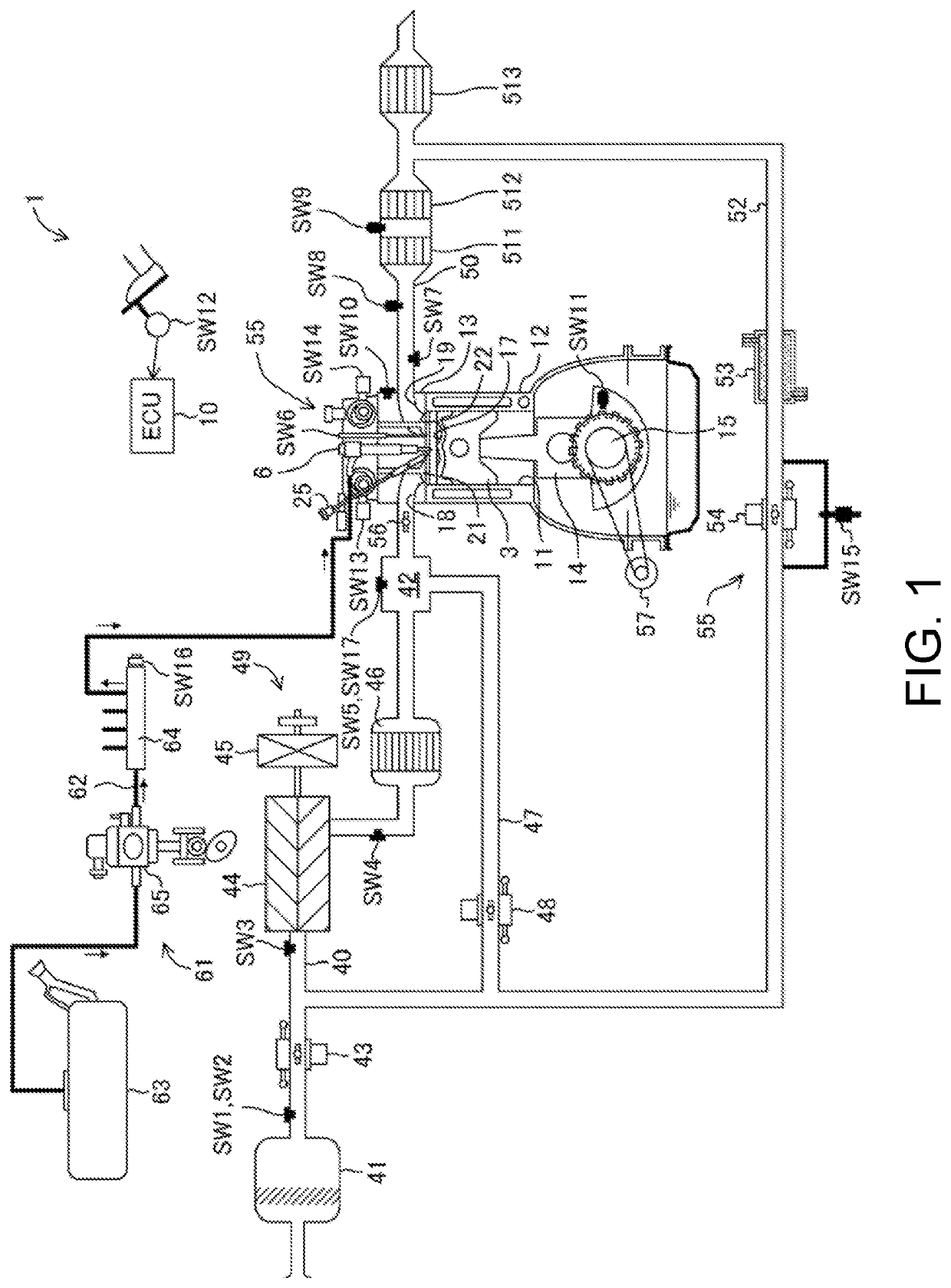
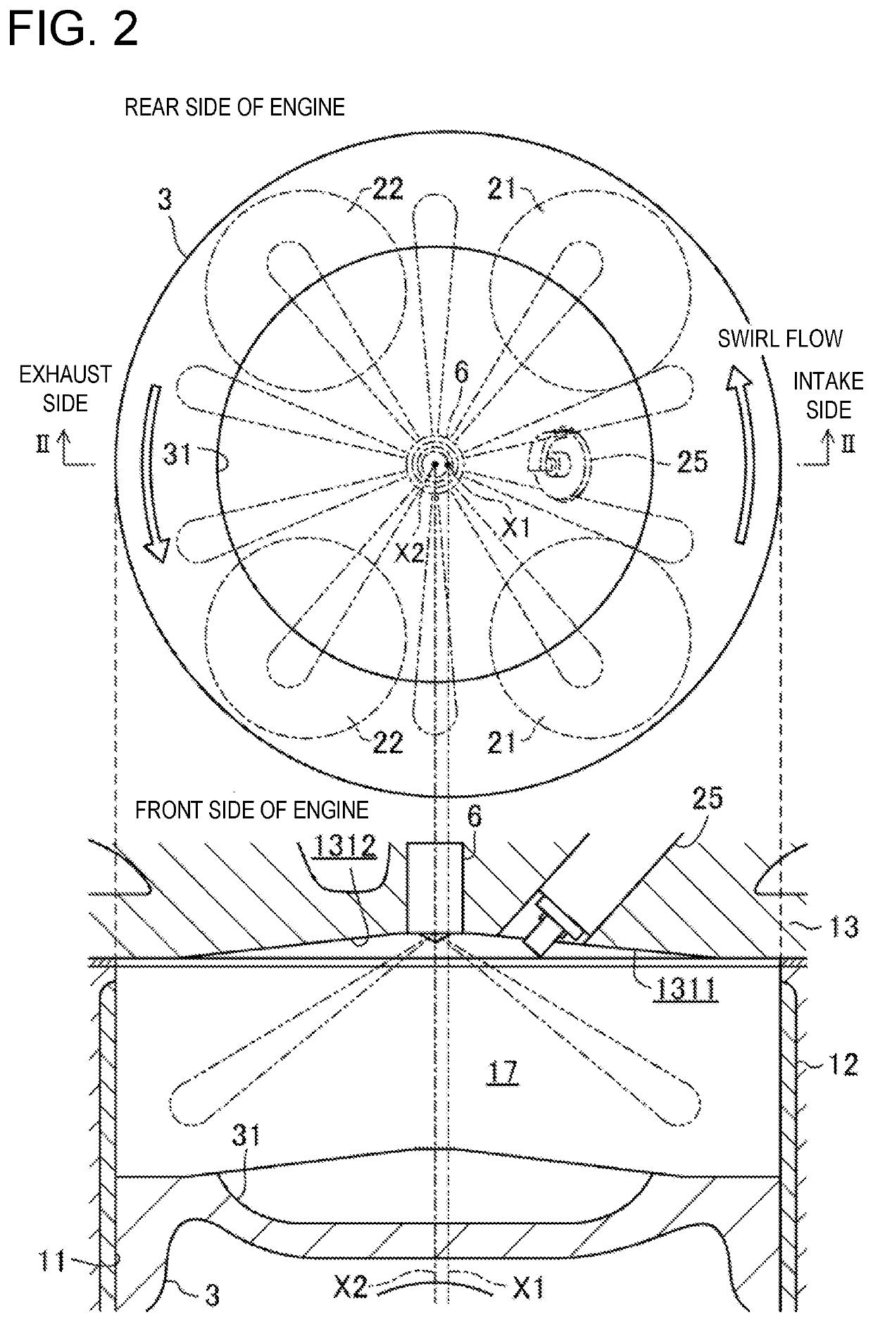
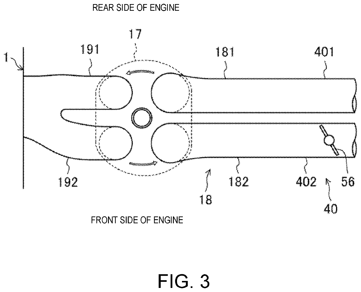
[0050]FIG. 1 is a view illustrating a configuration of the compression-ignition engine. FIG. 2 is a view illustrating a configuration of a combustion chamber of the engine. FIG. 3 is a view illustrating a configuration of the combustion chamber and an intake system. Note that, in FIG. 1, an intake side is the left side in the drawing, and an exhaust side is the right side in the drawing. In FIGS. 2 and 3, the intake side is the right side in the drawings, and the exhaust side is the left side in the drawings. FIG. 4 is a block diagram illustrating a configuration of a control system of the engine.

[0051]An engine 1 is a four-stroke engine which operates by combustion chambers 17 repeating an intake stroke, a compression stroke, an expansi...


PUM


Abstract

A control system for a compression ignition engine configured to start compression ignition combustion by igniting mixture gas formed by injecting fuel into combustion chambers is provided, which includes combustion chambers each defined in respective cylinders so that displacements of the combustion chambers change by respective pistons reciprocating, a throttle valve, ignition plugs, injectors, a sensor having measuring parts including an atmospheric-pressure detector configured to detect an atmospheric pressure, and configured to measure parameters related to operation of the engine, and a controller. The controller executes a lean compression ignition combustion control in which compression ignition combustion is performed at a given lean air-fuel ratio higher than a stoichiometric air-fuel ratio. The controller restricts the execution of the lean compression ignition combustion control when the controller determines that the atmospheric pressure is lower than a given threshold based on a signal outputted from the atmospheric-pressure detector.

Description

TECHNICAL FIELD[0001]The technology disclosed herein relates to a control system for a compression ignition engine.BACKGROUND OF THE DISCLOSURE[0002]It is known that combustion by compressed self-ignition in which a mixture gas combusts at once without flame propagation being intervened maximizes fuel efficiency because of the minimized combustion period. However, various problems of the combustion by compressed self-ignition need to be solved to be applied to automobile engines. For example, since the operating states and the environmental conditions vary greatly in the automotive application, it is a large problem to carry out a stable compressed self-ignition. In automobile engines, combustion by compressed self-ignition has not yet been put into practical use.[0003]In order to solve this problem, for example, WO2018 / 096744A1 proposes SPCCI (SPark Controlled Compression Ignition) combustion in which SI (Spark Ignition) combustion and CI (Compression Ignition) combustion are combi...

Claims


Application Information

Patent Timeline
IPC IPC(8): F02B1/14F02B19/10F02B53/06F02B27/02
CPCF02B27/0294F02B1/14F02B19/1085F02B53/06F02D37/02F02D41/0002F02D41/3041F02D41/1461F02D2200/703F02D2200/021F02D41/3064F02D41/3076F02D2200/0414F02D41/2422F02D2041/0015F02D41/0055F02D41/18F02D2250/24Y02T10/40Y02T10/12
Inventor MATSUSHIMA, YUTOHIGASHIO, MASAYOSHISUNAGARE, YUGOUTAKAYAMA, SHINJIUJIHARA, KENKOMASUDA, YUTA
Owner MAZDA MOTOR
Why Eureka
Try Eureka