
Three-Phase Wireless Power Transfer System And Three-Phase Wireless Chargeable Unmanned Aerial Vehicle System Based On The Same

a wireless charging and power transfer technology, applied in the direction of electric vehicle charging technology, charging stations, transportation and packaging, etc., can solve the problems of increasing the weight of the vehicle, affecting the operation of the vehicle, and the single-phase wpt has poor power transfer efficiency, so as to reduce the ripple in the output of the entire three-phase wireless charging system, reduce the intensity of the magnetic field formed around the wireless charging system, and reduce the effect of emi nois

Active Publication Date: 2018-03-01
KOREA ADVANCED INST OF SCI & TECH
View PDF20 Cites 43 Cited by
  • Summary
  • Abstract
  • Description
  • Claims
  • Application Information

AI Technical Summary

Benefits of technology

This patent describes a technology that allows drones to be charged wirelessly, which is useful because it eliminates the need to replace the battery. The drone has three power receiving coils that work together with a resonator to minimize reactive power in the system. This technology allows for convenient and efficient charging of the drone.

Problems solved by technology

However, the single-phase WPT has poor power transfer efficiency.
A strong electromagnetic field that occurs during wireless charging can cause damages or errors in its electronic components.
When a single-phase wireless charging system is applied to the UAV, there is a disadvantage in that, in addition to the disadvantages mentioned above, additional measures are required to prevent the electronic components from the electromagnetic interference (EMI), which causes increase in its weight.
However, in a wireless charging system using a single-phase inverter, the charging current is large and accordingly a strong magnetic field appears around the wireless charging system, thereby causing EMI noise or the like.

Method used


Image

  • Three-Phase Wireless Power Transfer System And Three-Phase Wireless Chargeable Unmanned Aerial Vehicle System Based On The Same
  • Three-Phase Wireless Power Transfer System And Three-Phase Wireless Chargeable Unmanned Aerial Vehicle System Based On The Same
  • Three-Phase Wireless Power Transfer System And Three-Phase Wireless Chargeable Unmanned Aerial Vehicle System Based On The Same

Examples


Embodiment Construction

[0045]Advantages and features of the present inventive concept and methods of accomplishing the same will become apparent with reference to the embodiments that will be described below in detail, along with the accompanying drawings. The present inventive concept may, however, be embodied in many different forms and should not be construed as limited to the exemplary embodiments set forth herein. Rather, these exemplary embodiments are provided so that this disclosure will be thorough and complete, and will fully convey the scope of the present inventive concept to those skilled in the art. In the drawings, the sizes and relative sizes of layers and regions may be exaggerated for clarity.

[0046]It will be understood that, although the terms first, second, third etc. may be used herein to describe various elements, these elements should not be limited by these terms. These terms are used to distinguish one element from another. Thus, a first element discussed below could be termed a s...


PUM


Abstract

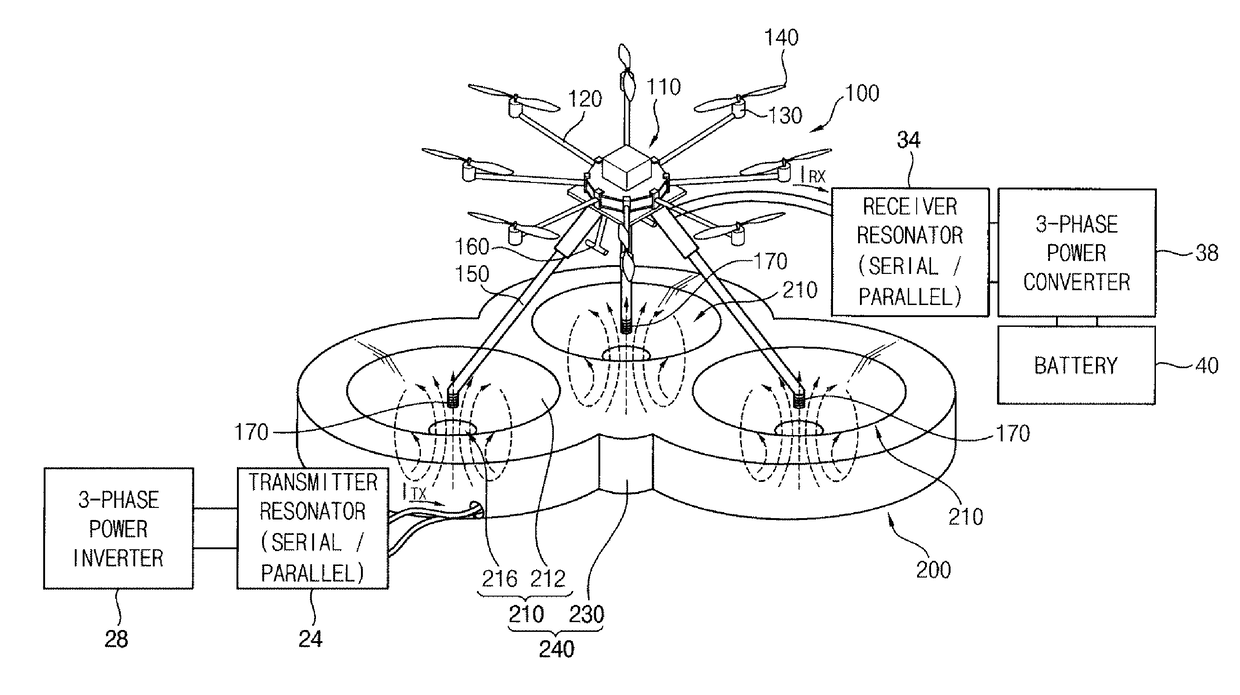
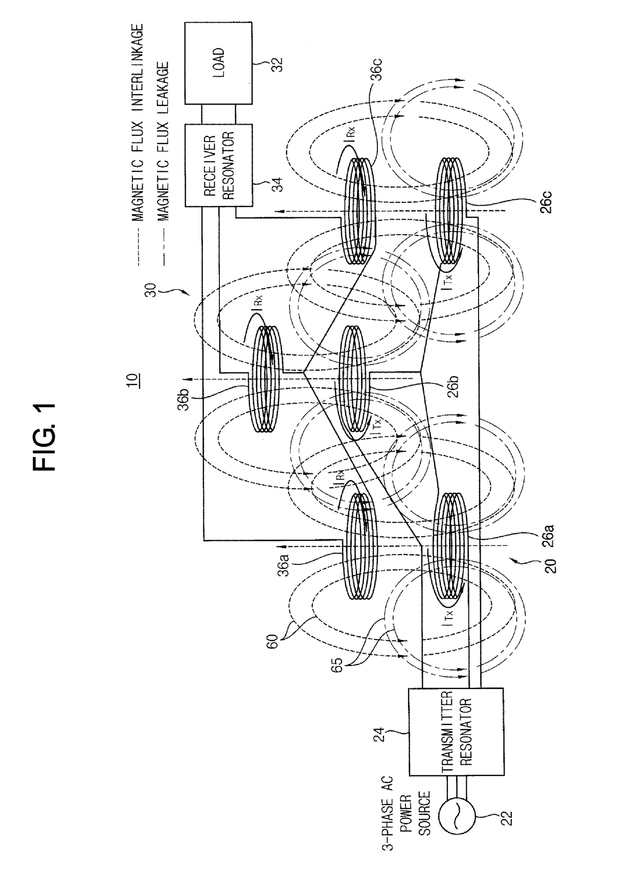
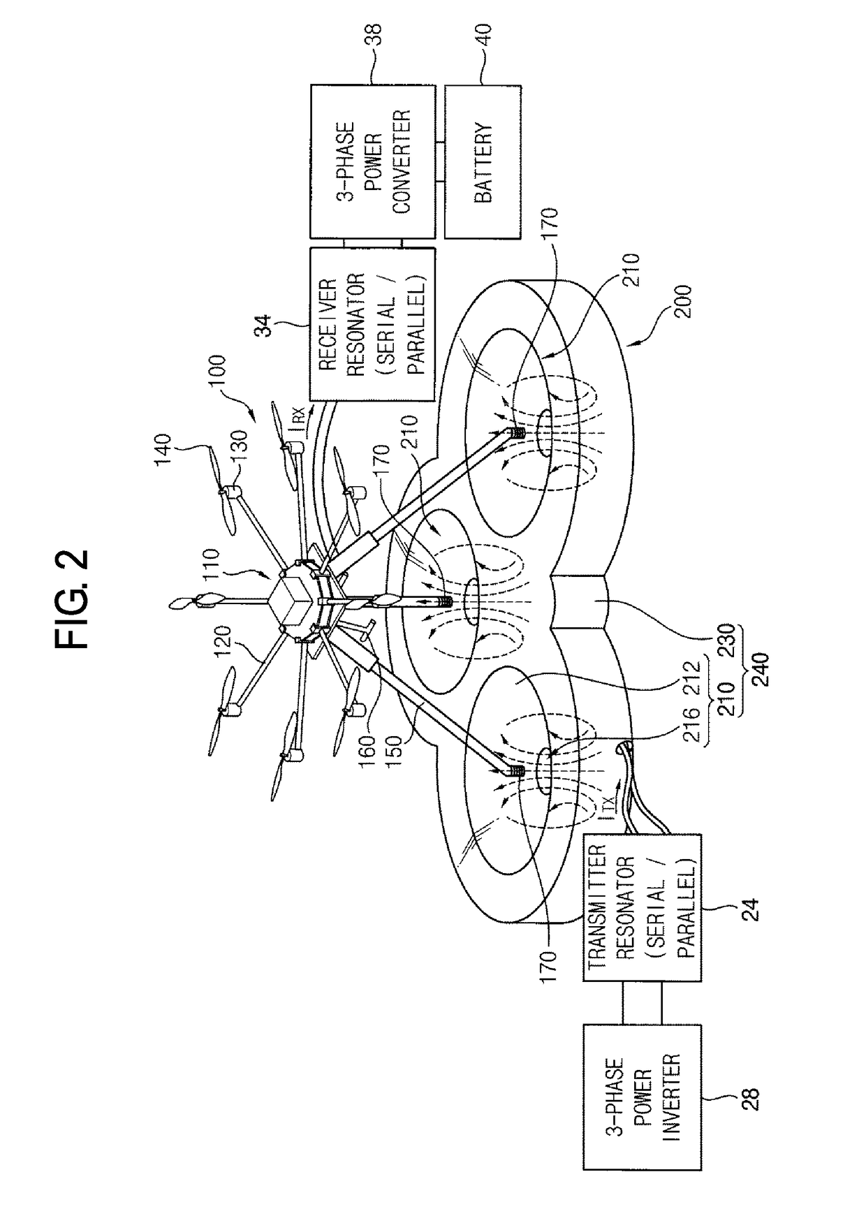
Disclosed are a three-phase wireless power transfer (WPT) system and three-phase wireless rechargeable unmanned aerial vehicle (UAV) system based on the same. Three power receiving coils, including resonators, are installed at the ends of three landing leg of the UAV. A three-phase power converter installed in the UAV receives the three-phase AC induction current induced in three power receiving coils, including resonators, converting the three-phase AC induction current into a DC current to be charged in a battery. A three-phase power wireless charging apparatus wirelessly transfers three-phase power from three power transmitting coils to the three power receiving coils of the UAV when the three landing legs land on three coil seating units provided on a charging platform. A magnetic flux leakage shielding coil may be provided to prevent magnetic flux leakage from approaching the UAV. The power transfer efficiency is excellent, and electromagnetic interference can be also reduced.

Description

CROSS-REFERENCE TO RELATED APPLICATION[0001]This application claims priority under 35 USC § 119 to Korean Patent Application No. 10-2016-0107444, filed on Aug. 24, 2016 in the Korean Intellectual Property Office (KIPO), the contents of which are herein incorporated by reference in their entirety.BACKGROUND1. Technical Field[0002]The present invention relates to a technology for a wireless power transfer (WPT) and its application to a wireless chargeable unmanned aerial vehicle (UAV), and more particularly to a technology for wirelessly charging three-phase AC power and a three-phase wireless chargeable UAV system based on the technology.2. Description of the Related Art[0003]Among the various devices driven by electric energy, there are many devices that need to supply the electric energy frequently through charging. Electric energy is charged in a wired manner in many devices, but in recent years the number of devices charged in a wireless manner is increasing.[0004]For example, th...

Claims


Application Information

Patent Timeline
Patent Type & Authority Applications(United States)
IPC IPC(8): B60L11/18B64C39/02
CPCB60L11/182B64C39/024B60L2210/30B60L2200/10B64C2201/042Y02T10/7072Y02T90/14B60L53/122B60L53/126Y02T10/72Y02T10/70B64U50/19B64U70/92B64U10/16B64U60/50B64U50/38H02J50/90H02J50/12B64C2025/325B64D27/24Y02T90/12B60L53/12B64U2201/104B64U2101/64
Inventor KIM, JOUNG-HOSONG, CHI-UK
Owner KOREA ADVANCED INST OF SCI & TECH
Learn More