
Telematics control system tracking and monitoring

a technology tracking system, which is applied in the field of telematics control system, can solve the problems of inability to accurately determine the fuel content of a vehicle, inability to timely and accurate record information into a system database, and inability to save time. , to achieve the effect of reducing power consumption, not wasting battery power, and saving tim

Inactive Publication Date: 2018-02-15
JAGUAR LAND ROVER LTD
View PDF4 Cites 17 Cited by
  • Summary
  • Abstract
  • Description
  • Claims
  • Application Information

AI Technical Summary

Benefits of technology

The sued invention is a system that can be used in a vehicle during the logistics stage (when the vehicle is being transported). The system includes a mode that allows it to function while the vehicle is in logistics mode (which is when the vehicle is being driven). The system uses opportunities when the vehicle's engine is turned on to avoid draining the battery. The system can also receive and process messages from off-board the vehicle to address any issues that may arise. The system includes a battery that is either connected to the vehicle's battery or a separate battery that powers the system when the vehicle battery is not connected. The system can check periodically to see if any messages have been received and will switch from a logistics quiet mode to a logistics activated mode only when necessary to minimize power consumption. This invention allows for monitoring and addressing issues with the vehicle's data during the logistics stage without draining the battery.

Problems solved by technology

The logistics of transporting finished vehicles from a manufacturing production line to a dealership where the vehicle will be sold gives rise to many problems.
This is a particular issue when transporting vehicles on a global scale, including to different regions and markets.
These problems may arise from inter alia a lack of timely and accurate recordation of information into a system database.
Current systems rely on manual input which can be inefficient and unreliable.
Firstly, a problem that arises during transportation is the inability to determine accurately how much fuel is in a vehicle at a given point in time.
In addition, vehicle status issues may arise during transportation, such as batteries becoming flat and needing replacement or tyre pressures being too low.
At present, this may go undetected and unreported, resulting in delays in providing a fully-functioning vehicle to the end user.
Also, if information relating to the geographical location of the vehicles is not entered into a system then this leads to inaccuracies in, and the inability to manage, the global inventory.
This can lead to poor decisions being made regarding, for example, the volume of vehicles that need to be transported to a certain region.
Current vehicles may have externally-fitted tracking devices (e.g. RFID tags); however, they are lost easily and are subject to both initial costs (e.g. tracking infrastructure) and ongoing costs (e.g. annual service charge).
Next, the present systems may lead to cash flow problems.
Since processes may be manual, non-standard, slow, complex and / or difficult to monitor, this can lead to delayed revenue realisation and hence can have a significant cost impact.
Current systems may also lead to a lack of compliance; for example, delays in notification by a dealer that a vehicle has arrived at a dealership, or that a vehicle has passed a particular check point (e.g. a port) during transportation.
Different organisations may place varying degrees of importance on certain protocols which leads to these delays in notification of vehicle arrival or movement.

Method used


Image

  • Telematics control system tracking and monitoring
  • Telematics control system tracking and monitoring
  • Telematics control system tracking and monitoring

Examples


Embodiment Construction

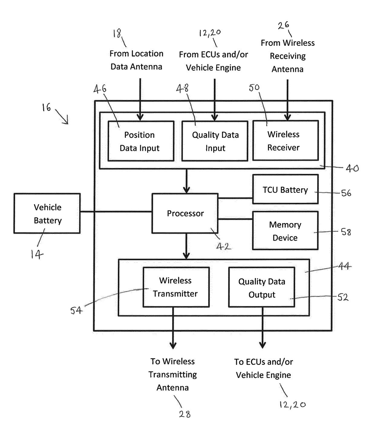
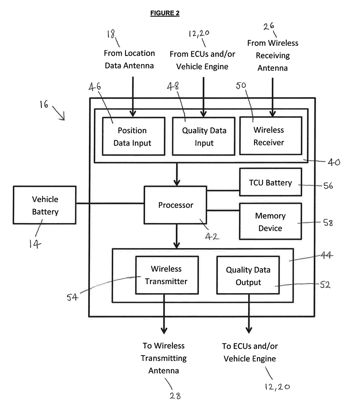
[0035]FIG. 1 shows one embodiment of a vehicle 10 with a vehicle engine 12 and a vehicle battery 14, the vehicle 10 also including a telematics control unit (TCU) or telematics control system 16 for carrying out a method according to an aspect of the present invention. In addition, the vehicle 10 includes a vehicle location data antenna or sensor 18 for receiving location data relating to the current location of the vehicle 10. For example, the location data antenna 18 may be a Global Positioning System (GPS) antenna for receiving signals from a GPS satellite, or could be compound, multiple or substitutable antennas for receiving from other positioning systems such as GLONASS, BeiDou or Galileo. The TCU 16 is in communication with one or more other electronic control units (ECUs) 20 via a controller area network (CAN) 22, or other vehicle network infrastructure such as TT Ethernet or Flexray. For example, the ECUs 20 may be for monitoring and / or controlling so-called vehicle feature...


PUM


Abstract

The present invention provides a telematics control system for use in a vehicle for determining whether to transmit vehicle data to off-board the vehicle, the vehicle including a vehicle battery and one or more vehicle sensors. The system includes an input arranged to receive vehicle data from at least one of the one or more on-board vehicle sensors, a processor arranged to determine whether the vehicle battery is operably connected to the system, and an output arranged to transmit a wireless communications message indicative of the received vehicle data to off-board the vehicle. The system further includes a logistics activated mode in which it is operable to transmit communications messages and a logistics quiet mode in which it draws no power from the vehicle battery. The processor is operable to switch from the logistics quiet mode to the logistics activated mode when it determines that the vehicle battery is operably connected to the system, and in the logistics activated mode to send the communications message from the output, so as to transmit vehicle data to off-board the vehicle.

Description

TECHNICAL FIELD[0001]The present disclosure relates to a telematics control system for use in a vehicle and particularly, but not exclusively to a system that is operable in a logistics mode to transmit vehicle data to off-board the vehicle. Aspects of the invention relate to a system, to a method, and to a vehicle.BACKGROUND[0002]The logistics of transporting finished vehicles from a manufacturing production line to a dealership where the vehicle will be sold gives rise to many problems. This is a particular issue when transporting vehicles on a global scale, including to different regions and markets. These problems may arise from inter alia a lack of timely and accurate recordation of information into a system database. Current systems rely on manual input which can be inefficient and unreliable. The information that is to be input may include a vehicle's current geographical location during transportation to a dealership, or details of pre-sale maintenance checks.[0003]Examples ...

Claims


Application Information

Patent Timeline
Patent Type & Authority Applications(United States)
IPC IPC(8): G07C5/00G07C5/08G06Q10/08
CPCG07C5/008G06Q10/08G07C5/08B60W2550/40G07C5/0808Y02D10/00B60W2556/45
Inventor BUSWELL, DEBORAHLOWE, TONYBURNET, MARK
Owner JAGUAR LAND ROVER LTD
Learn More