
Apparatus and method for controlling stability of unmanned aerial vehicle

a technology for unmanned aerial vehicles and apparatus, applied in vehicle position/course/altitude control, process and machine control, instruments, etc., can solve the problems of inability to maintain stability and small-sized unmanned aerial vehicles to be easily controlled, and achieve the effect of minimizing the risk of an acciden

Active Publication Date: 2018-02-15
UNIST ULSAN NAT INST OF SCI & TECH
View PDF5 Cites 16 Cited by
  • Summary
  • Abstract
  • Description
  • Claims
  • Application Information

AI Technical Summary

Benefits of technology

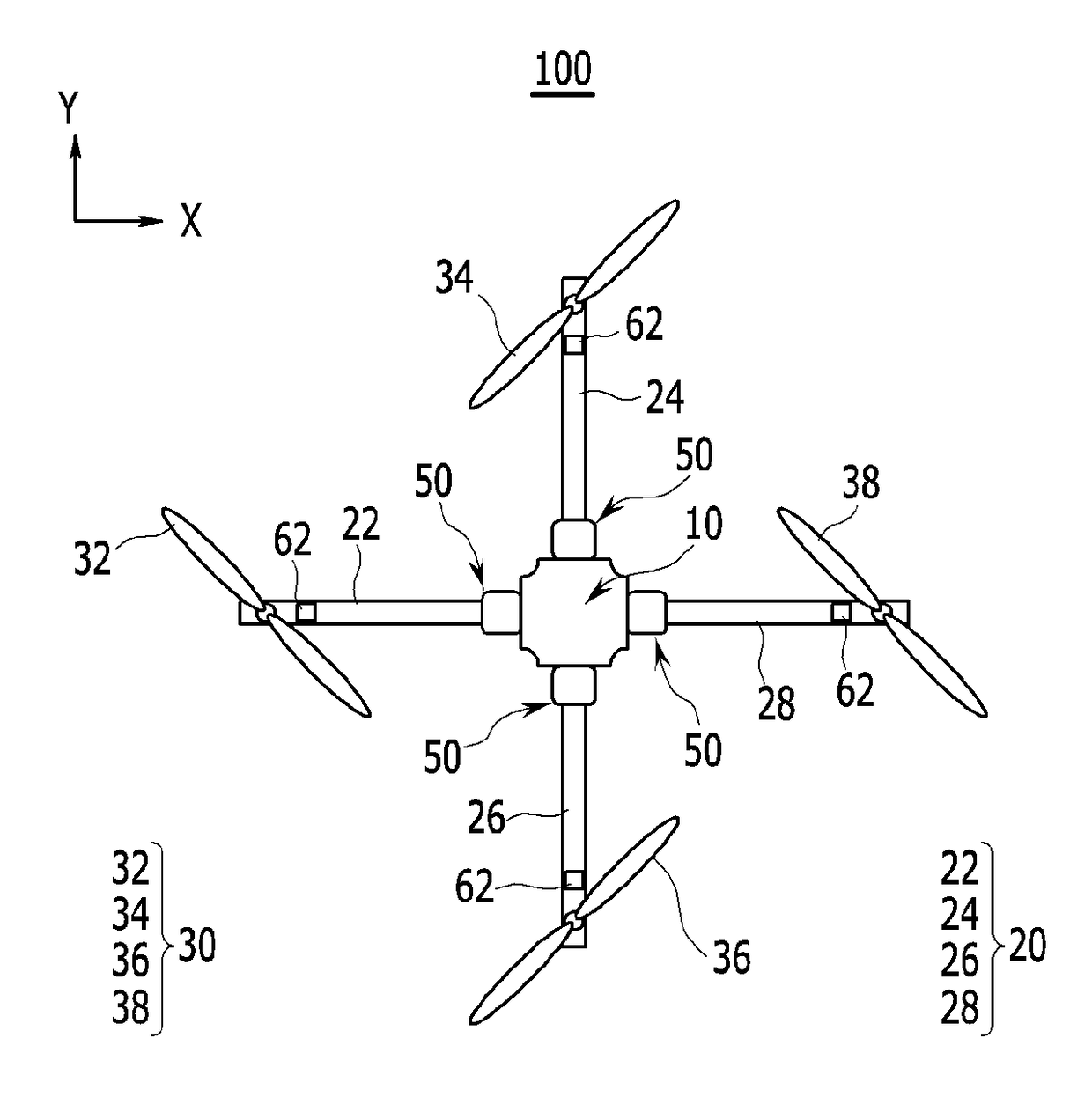
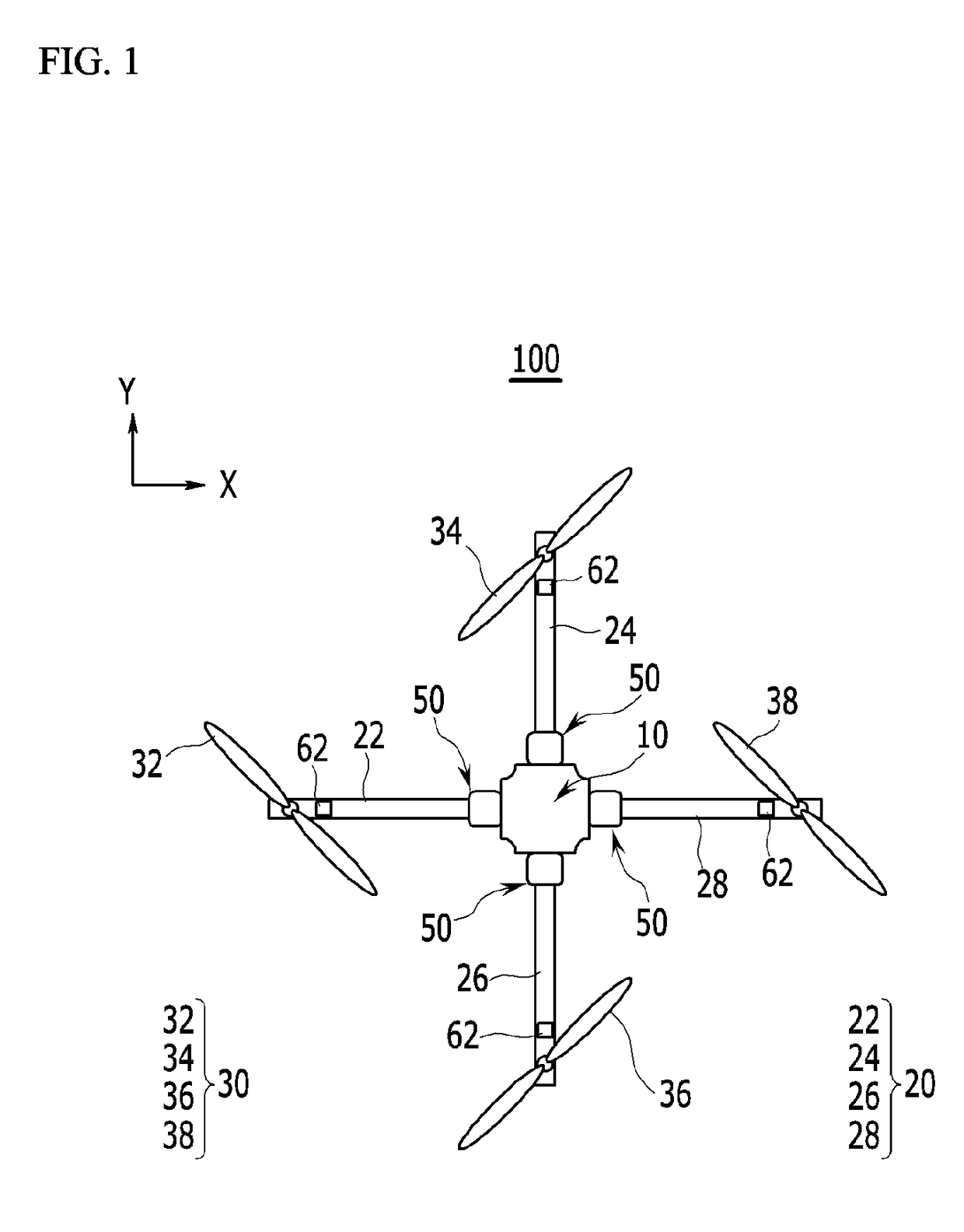
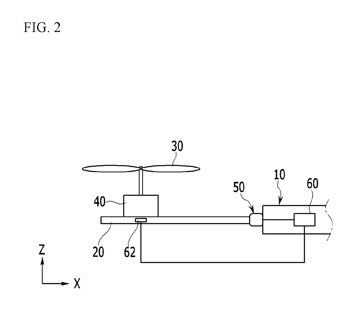
The present invention provides an unmanned aerial vehicle that can maintain stability by changing positions of rotating rotors when one of the rotating rotors malfunctions, and a method for controlling stability of the unmanned aerial vehicle. Additionally, the unmanned aerial vehicle can conveniently and promptly deal with an emergency situation that may occur during flight, and a method for controlling stability of the unmanned aerial vehicle. The unmanned aerial vehicle can be prevented from being crushed by promptly handling an emergency situation, thereby minimizing a risk of an accident.

Problems solved by technology

However, a conventional unmanned aerial vehicle is small-sized and stability of the small-sized unmanned aerial vehicle cannot be easily controlled, and when one of the plurality of rotating rotors malfunctions and thus stops operating, the horizontal stability cannot be maintained, thereby causing a crash.

Method used


Image

  • Apparatus and method for controlling stability of unmanned aerial vehicle
  • Apparatus and method for controlling stability of unmanned aerial vehicle
  • Apparatus and method for controlling stability of unmanned aerial vehicle

Examples


Embodiment Construction

[0027]The terminologies used herein are set forth to illustrate a specific exemplary embodiment, but do not intend to limit the present invention. Singular expressions used herein include plural expressions unless they have definitely opposite meanings. It will be further understood that the terms “comprises” and / or “comprising,” when used in this specification, specify the presence of stated properties, regions, integers, steps, operations, elements, and / or components, but do not preclude the presence or addition of one or more other properties, regions, integers, steps, operations, elements, components, and / or groups.

[0028]Hereinafter, the present invention will be described more fully hereinafter with reference to the accompanying drawings, in which exemplary embodiments of the invention are shown. As easily understood by the person with ordinary skill in the art to which the present invention pertains, the exemplary embodiments which will be described below may be variously modi...


PUM


Abstract

The present invention provides an unmanned aerial vehicle that can maintain stability by changing positions of rotating rotors when one of the rotating rotors malfunctions, and a method for controlling stability of the unmanned aerial vehicle. The unmanned aerial vehicle includes: a main body; a plurality of support bars that are arranged while forming an angle with each other along a circumferential direction of the main body and extended to an outer side from the main body; a plurality of rotating rotors that are respectively provided to the support bars and generate thrust; motors that are respectively connected to the rotating rotors to drive the rotating rotors; drivers that change positions of the respective rotating rotors along the circumferential direction of the main body by moving the support bars with respect to the main body; and a controller that maintains horizontal stability of the main body by controlling the drivers.

Description

CROSS-REFERENCE TO RELATED APPLICATION[0001]This application claims priority to and the benefit of Korean Patent Application No. 10-2016-0102334 filed in the Korean Intellectual Property Office on Aug. 11, 2016, the entire contents of which are incorporated herein by reference.BACKGROUND OF THE INVENTION(a) Field of the Invention[0002]The present invention relates to an unmanned aerial vehicle. More particularly, the present invention relates to an unmanned aerial vehicle that can be easily balanced when the vehicle malfunctions, and a method for controlling stability of the unmanned aerial vehicle.(b) Description of the Related Art[0003]In general, an unmanned aerial vehicle (UAV), which is called a drone, is an aerial vehicle that files by radio-control without carrying a human pilot, and the use of unmanned aerial vehicles for various purposes such as aerial photography, transportation of goods, and the like has explosively increased.[0004]The unmanned aerial vehicle is equipped ...

Claims


Application Information

Patent Timeline
IPC IPC(8): B64C39/02B64C27/14B64C27/08
CPCB64C39/024B64C27/08B64C27/14B64C2201/165B64C2201/042B64C2201/108B64C2201/027B64U10/13B64U2201/00B64U10/14B64U40/10B64U30/296B64C27/52B64D45/00B64U10/10B64U50/19B64U30/20B64U50/13
Inventor BAEK, WOONGKIPARK, SEONG BEOM
Owner UNIST ULSAN NAT INST OF SCI & TECH
Learn More