
Sexual stimulation device using light therapy, vibration and physiological feedback

a technology of light therapy and physiological feedback, applied in the field of female sexual stimulation devices, can solve the problems of reducing the stimulation effect, and no device of the prior art utilizes physiological sensors

Active Publication Date: 2018-02-15
ZIPPER RALPH
View PDF9 Cites 19 Cited by
  • Summary
  • Abstract
  • Description
  • Claims
  • Application Information

AI Technical Summary

Benefits of technology

The present invention is a female sexual stimulation device that uses therapeutic light energy to enhance genital blood flow and improve sexual response. The device and method may cause greater clitoral swelling, improved genital blood flow, and enhanced orgasms. Additionally, the invention may use specific wavelengths of light to decrease bacterial and fungal populations in the vagina, vulva, clitoris, and penis. Overall, this invention offers a more effective and safe way to stimulate the female sexual response.

Problems solved by technology

None of the devices of the prior art utilize physiological sensors to monitor the physiologic parameters of a user and changes thereto that are experienced while a user is using the device for sexual stimulation; nor do the aforementioned devices utilize data provided by physiological sensors to change at least one parameter of sexual simulation being applied to a user's body by the sexual stimulation device, or alert the user of such physiologic states and or changes thereto.
One drawback with the prior art method described above is that it requires mental concentration by a user during sexual stimulation by a sexual stimulation device; however, this mental concentration may act to reduce the effect of the stimulation because, generally, it is desired that a user remain mentally relaxed in order to achieve maximum effects of sexual stimulation.
Another drawback of the prior art method described above is that user assessments of physiologic conditions by simple feeling are subjective.
Such feelings are not objective measurements of the actual physiological conditions of a user of a sexual stimulation device.
The subjective assessments made by the user are thus prone to error and misinterpretation, leading to decisions on the part of the user to vary at least one parameter of sexual simulation being applied to a user's body by the sexual stimulation device in a non-optimum manner Additionally, the prior art method described above requires the user to be distracted, at least momentarily, to interact with the control interface of the device.
This method of effecting volitional changes in the device behavior with button pushes or similar based upon subjective assessment of physiologic states is flawed.
One problem with this method is that it requires a certain level of mental concentration by the user in a situation that would otherwise demand mental relaxation.
Another problem is that subjective assessments of physiologic states are not objective data collections and, as such, are prone to error.
Additionally, this method requires the user to be distracted, at least momentarily, to interact with the control interface of the device.

Method used


Image

  • Sexual stimulation device using light therapy, vibration and physiological feedback
  • Sexual stimulation device using light therapy, vibration and physiological feedback
  • Sexual stimulation device using light therapy, vibration and physiological feedback

Examples


embodiment 850

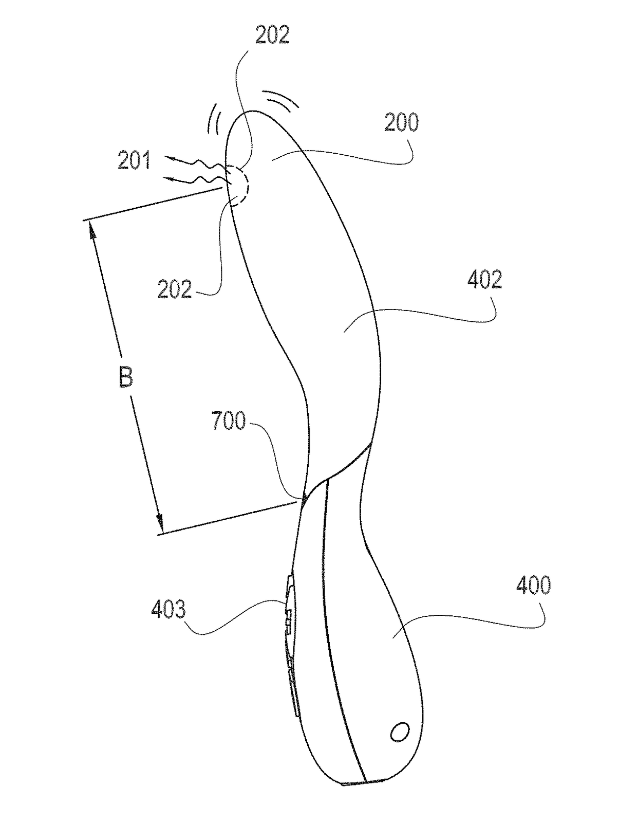
[0136]Referring now to FIG. 16, three optional locations the pulse oximeter of the invention are depicted: the invention may comprise a pulse oximeter at any one, any combination, or all three locations. In first pulse oximeter embodiment 850 in vaginal finger 200, the invention may comprise a reflective pulse oximeter as shown in FIG. 14 in which pulse oximeter light source 801 transmits light energy D as described above which is reflected from the body surface of a user C, which may be the user's posterior vaginal wall. Reflected light energy E is received by pulse oximeter light sensor 802, and the received signal is processed by pulse oximeter circuitry 875 located on pulse oximeter printed wiring board 803 (not shown in FIG. 14)) as described above, and the processed signal containing pulse rate or oxygen saturation is communicated to controller 510 by pulse oximeter wiring 805.

embodiment 851

[0137]Still referring to FIG. 16, in a second pulse oximeter embodiment 851 in the handle 400, the invention may comprise a reflective pulse oximeter as shown in FIG. 14 in which pulse oximeter light source 801 transmits light energy D as described above which is reflected from the body surface of a user C, which may be the user's hand. Reflected light energy E is received by pulse oximeter light sensor 802, and the received signal is processed by pulse oximeter circuitry 875 located on pulse oximeter printed wiring board 803 (not shown in FIG. 14) as described above, and the processed signal containing pulse rate or oxygen saturation is communicated to controller 510 by pulse oximeter wiring 805.

[0138]Still referring to FIG. 16, in a third pulse oximeter embodiment 852 in the handle 400, the invention may comprise a transmissive pulse oximeter as shown in FIG. 14 in which pulse oximeter light source 801 transmits light energy D as described above which is transmitted through a user...


PUM


Abstract

A sexual stimulation apparatus and method which may comprise a plurality of light sources for photostimulation of the vagina, clitoris, or both; one or more vibrators for mechanical stimulation of an area of the vagina; a handle; a controller and programmable memory for containing non-transitory instructions for modes of operation and driving the light sources and vibrators of the invention; a vaginal finger; a handle for ease of use; a keypad for user entry of commands; and a charging or programming port. The invention may also comprise sensors that sense physiologic parameters of a user and adjust sexual stimulation parameters to achieve a desired sexual stimulation effect. Blood oxygen level, temperature, pulse rate and muscle electrical activity may be sensed. The invention also may comprise a flexible covering that provides smooth sliding engagement with an area of the vagina of a user.

Description

CROSS REFERENCE TO RELATED APPLICATIONS[0001]This application is a continuation-in-part (CIP) of non-provisional patent application Ser. No. 14 / 681,943, titled SEXUAL STIMULATION DEVICE USING LIGHT THERAPY, VIBRATION, AND PHYSIOLOGICAL FEEDBACK, which was filed in the United States Patent and Trademark Office (USPTO) on Apr. 8, 2015 which is herein incorporated by reference in its entirety, which is a continuation-in-part (CIP) application of non-provisional application Ser. No. 14 / 456,151 titled IMPROVED SEXUAL STIMULATION METHOD USING LIGHT THERAPY, filed in the USPTO on Aug. 11, 2014 and issued from the USPTO as U.S. Pat. No. 9,610,214 on Apr. 4, 2017, which is herein incorporated by reference in its entirety and which was a divisional of non-provisional application Ser. No. 13 / 828,445 filed in the USPTO on Mar. 14, 2013 titled SEXUAL STIMULATION DEVICE USING LIGHT THERAPY, now issued as U.S. Pat. No. 8,801,600 on Aug. 12, 2014, which is also incorporated herein by reference in i...

Claims


Application Information

Patent Timeline
Patent Type & Authority Applications(United States)
IPC IPC(8): A61H19/00A61H23/02A61N5/06A61H23/00A61H7/00
CPCA61H19/40A61N5/0622A61H23/006A61N2005/0611A61H2201/5097A61H2201/5038A61H2201/5015A61H2201/501A61H2201/5005A61H2201/10A61H23/0263A61H19/44A61H19/34A61H7/003A61N5/0624A61H2201/0153A61H23/00A61H2201/5061A61H2230/045A61H2230/085A61H2230/208A61N5/0603
Inventor ZIPPER, RALPH
Owner ZIPPER RALPH
Learn More