Front passenger seat airbag device

a front passenger seat and airbag technology, which is applied in the direction of pedestrian/occupant safety arrangement, vehicular safety arrangments, vehicle components, etc., can solve the problems of substantially uniform deployment load, airbag door cannot be substantially uniformly opened on both left and right sides, and spacers or the like might fall off the back face, so as to reduce the damage to the second airbag section due to high temperature gas generated by the inflator, and the damage to the first airbag section may be reduced

Active Publication Date: 2018-02-08
TOYOTA JIDOSHA KK +1
View PDF0 Cites 10 Cited by
  • Summary
  • Abstract
  • Description
  • Claims
  • Application Information

AI Technical Summary

Benefits of technology

[0052]Note that in the present configuration, the total opening area of the seventh flow-regulating hole is set larger than the total opening area of the sixth flow-regulating hole, such that gas generated by the cylinder-type inflator is distributed in good balance to the first airbag section and the second airbag section. Moreover, the height of the first support face with respect to the second support face may be easily changed by changing the shape of the fourth flow-regulating member (the height of the third step portion). Furthermore, damage to the first airbag section due to high temperature gas generated by the inflator being directly received by the first airbag section may be reduced. Similarly, damage to the second airbag section due to high temperature gas generated by the inflator being directly received by the second airbag section may also be reduced.
[0053]Thus, the present configuration enables suitable amounts of gas generated by the inflator to be respectively supplied to the first airbag section and the second airbag section, enables the height of the first support face with respect to the second support face to be easily adjusted, and also enables damage to the first airbag section and the second airbag section due to the heat of the gas to be reduced.

Problems solved by technology

However, in the case of the front passenger seat airbag device described in the above documents, configuration is such that the spacer or the like is set on the first airbag section side of the back face of the airbag door, such that the first airbag section forcefully strikes the spacer when the front passenger seat airbag is inflated and deployed.
It is therefore conceivable that the spacer or the like might fall off the back face of the airbag door.
However, a different issue arises in the case of the front passenger seat airbag device described in JP-A No. 2015-231808.
Thus, in the case of this front passenger seat airbag device, a substantially uniform deployment load cannot be made to act on the back face of the airbag door and the airbag door cannot be made to open out substantially uniformly on both left and right sides.
Thus, in the technology of the documents described above, it is difficult to both prevent a spacer from falling off or the like during inflation and deployment of the first airbag section, and to open out an airbag door substantially uniformly so as to stabilize the deployment behavior of the front passenger seat airbag having a left-right asymmetrical structure, and there is room for improvement of the technology described in the above documents regarding these points.
In a configuration has been employed in which a spacer or its equivalent is provided as a raising member at a back face of an airbag door, it would be conceivable that a first airbag section might catch on the spacer or its equivalent in the inflation and deployment process of a front passenger seat airbag, such that an excessive deployment load would act on the spacer or its equivalent.
Thus, when output from the first inflator alone is insufficient, this shortage may be made up by the second inflator.

Method used


Image

  • Front passenger seat airbag device
  • Front passenger seat airbag device
  • Front passenger seat airbag device

Examples


first exemplary embodiment

[0067]Overall Configuration of First Exemplary Embodiment

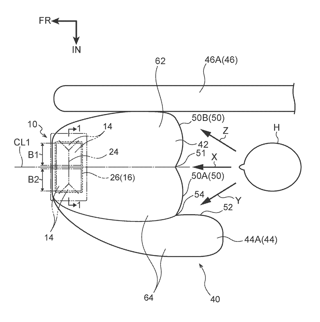
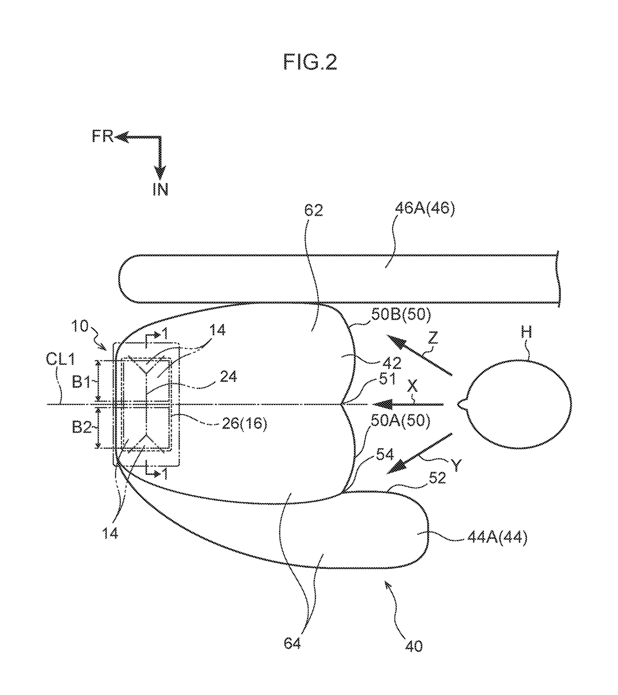
[0068]Explanation follows regarding a front passenger seat airbag device 10 according to the first exemplary embodiment, with reference to FIG. 1 to FIG. 5. Note that in these drawings, the arrow FR indicates the vehicle front side, the arrow UP indicates the vehicle upper side, and the arrow IN indicates the vehicle width direction inner side. The front passenger seat airbag device 10 indicated in the respective drawings is employed in a left-hand drive vehicle.

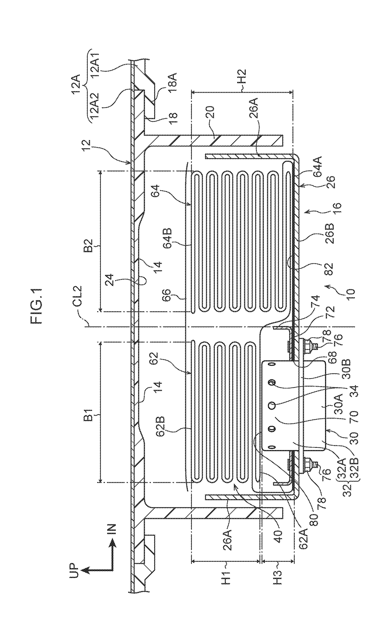
[0069]As illustrated in FIG. 3, the front passenger seat airbag device 10 is installed on the vehicle lower side of an upper face portion 12A on the front passenger seat side of an instrument panel 12. The front passenger seat airbag device 10 is configured by airbag doors 14 provided on the upper face portion 12A side and an airbag module 16 disposed on a back face side (i.e., vehicle lower side) of the airbag doors 14.

[0070]As illustrated in FIG. 1, the upper face po...

second exemplary embodiment

[0111]Explanation follows regarding a front passenger seat airbag device 90 according to the second exemplary embodiment of the present disclosure, with reference to FIG. 6. Components that are similar to as those in the previously-described first exemplary embodiment are appended with the same reference numerals, and explanation thereof is omitted.

[0112]As illustrated in FIG. 6, the feature of the front passenger seat airbag device 90 according to the second exemplary embodiment is that a diffuser 92, serving as a “first flow-regulating member” has been added to the configuration of the previously-described first exemplary embodiment.

[0113]The diffuser 92 is made of metal and installed in an inner portion of the front passenger seat airbag 40. The diffuser 92 includes a first flow-regulating portion 94 disposed on the first airbag section 62 side, a second flow-regulating portion 96 disposed on the second airbag section 64 side, and a step portion 98 serving as a “first step portio...

third exemplary embodiment

[0124]Explanation follows regarding a front passenger seat airbag device 110 according to the third exemplary embodiment of the present disclosure, with reference to FIG. 7. Components that are similar to those in the previous exemplary embodiments are appended with the same reference numerals, and explanation thereof is omitted (this point similarly applies to the fourth exemplary embodiment onward, described later).

[0125]As illustrated in FIG. 7, a first inflator 112 configured by a circular disk-type inflator is disposed on the first airbag section 62 side in the front passenger seat airbag device 110. Not only is a disk-type inflator disposed on the first airbag section 62 side, but a second inflator 114 configured by a circular disk-type inflator is also disposed on the second airbag section 64 side. Since two inflators, these being the first inflator 112 and the second inflator 114, are employed, an airbag retainer 116 is larger in size, such that the two inflators that are th...


PUM


Abstract

A front passenger seat airbag device includes a module case; a front passenger seat airbag configured such that, in a folded state, a height of a first airbag section positioned at a vehicle outer side is lower than a height of a second airbag section positioned at a vehicle inner side, and widths of the first airbag section and the second airbag section are substantially the same; an inflator disposed at a bottom side of the module case; and a raising member disposed at a bottom portion of the module case, and that raises a height of a first support face supporting the first airbag section to be higher than a height of a second support face supporting the second airbag section, such that a height of an upper face of the first airbag section is substantially aligned with a height of an upper face of the second airbag section.

Description

CROSS-REFERENCE TO RELATED APPLICATION[0001]This application is based on and claims priority under 35 USC 119 from Japanese Patent Application No. 2016-154061 filed on Aug. 4, 2016, the disclosure of which is incorporated by reference herein.BACKGROUNDTechnical Field[0002]The present disclosure relates to a front passenger seat airbag device.Related Art[0003]Front passenger seat airbags are conventionally known that include a first airbag section inflated and deployed at the vehicle front side of an occupant seated in a front passenger seat, and a second airbag section positioned at the vehicle width direction inner side of the first airbag section and bulging out further toward the vehicle rear side than a rear end of the first airbag section (see, for example, Japanese Patent Application Laid-Open (JP-A) Nos. 2016-037127 and 2015-231808). Since a front passenger seat airbag with the above structure has left-right asymmetry in a vehicle plan view, it may be referred to as a “front ...

Claims


Application Information

Patent Timeline
Patent Type & Authority Applications(United States)
IPC IPC(8): B60R21/262B60R21/237B60R21/232B60R21/2334B60R21/205B60R21/213
CPCB60R21/262B60R21/0136B60R21/213B60R21/232B60R21/2334B60R21/237B60R2021/0004B60R2021/0006B60R2021/0009B60R2021/0023B60R2021/0048B60R21/2165B60R21/217B60R2021/23107B60R21/264B60R2021/01286B60R2021/01027B60R21/205B60R21/2176B60R21/26B60R2021/26058B60R21/231B60R2021/23161
Inventor OHNO, MITSUYOSHIYAMADA, IKUOHAYASHI, MIKINEITO, SHUNKOJIMA, TAKAHIRO
Owner TOYOTA JIDOSHA KK
Why Eureka
Try Eureka