
Separator comprising adhesive coating parts having different tack strengths and electrode assembly comprising the same

a technology of adhesive coating parts and electrode assemblies, which is applied in the field of separation, can solve the problems of increasing internal resistance, deteriorating the overall performance of the secondary battery, and increasing the cases of defective appearance of the electrode assembly

Active Publication Date: 2018-02-01
LG ENERGY SOLUTION LTD
View PDF2 Cites 10 Cited by
  • Summary
  • Abstract
  • Description
  • Claims
  • Application Information

AI Technical Summary

Benefits of technology

The present patent application describes a new electrode assembly for secondary batteries that improves production yield, life expectancy, and high rate charging / discharging characteristics. This is achieved by incorporating a separator made of a sheet-like porous substrate with different adhesive coatings having different tack strengths. The thickness of the adhesive coatings should be between 2 μm to 20 μm, with 4 μm to 10 μm being ideal. If the adhesive coating is too thin, it may not provide enough stability, while if it is too thick, it may lower energy density and cause the adhesive coating to easily detach from the separation film.

Problems solved by technology

On the other hand, the secondary battery repeatedly contracts and expands in the process of charging and discharging, which may generate a space between an electrode and a separator.
With a space introduced between the electrode and the separator, lithium ions need to move further, increasing the internal resistance and deteriorating the overall performance of the secondary battery.
However, when applied to electrode assemblies requiring winding of the separator in the manufacturing process, the conventional method causes one end of the electrode assembly to be stuck to a winding core during their subsequent separation, which is called “tail out condition,” resulting in increased cases of defective appearance of the electrode assembly.

Method used


Image

  • Separator comprising adhesive coating parts having different tack strengths and electrode assembly comprising the same
  • Separator comprising adhesive coating parts having different tack strengths and electrode assembly comprising the same
  • Separator comprising adhesive coating parts having different tack strengths and electrode assembly comprising the same

Examples


example

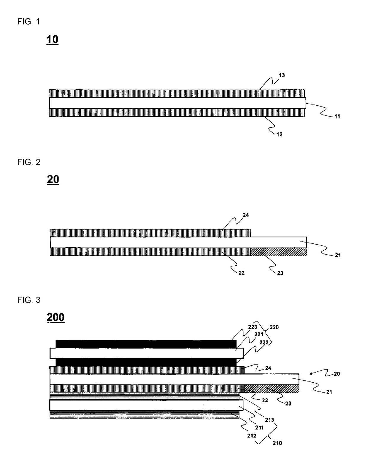
[0125]As shown in FIG. 2, a first adhesive coating part having an acrylic pressure sensitive adhesive as a first pressure sensitive adhesive was formed on the first surface of the sheet-like porous substrate, and a second adhesive coating part was formed with PVdF that is a fluorine-based pressure sensitive adhesive. And a third coating part having an acrylic pressure sensitive adhesive was formed as a third pressure sensitive adhesive on the second surface of the sheet-shaped porous substrate to produce a separator.

experimental example

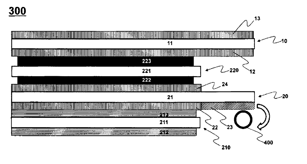
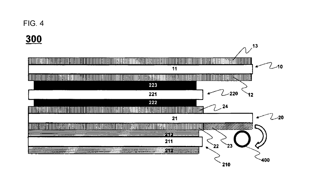
[0127]A negative electrode, a separator and a positive electrode were stacked to the separators prepared in Example and Comparative Example so that the first coating part faces the negative electrode and the third coating part faces the positive electrode (see FIG. 3). The winding was then carried out with the winding core brought into contact with the second adhesive coating part (see FIG. 4).

[0128]From this, it was judged whether or not the separator was defective by confirming the degree of the separator being pulled out when separating the winding core. The results are shown in Tables 1 and 2 below.

[0129]Ten jelly-roll type electrode assemblies including the separators according to Example and ten jelly-roll type electrode assemblies including the separators according to Comparative Example were respectively fabricated, and the above experiment was repeated (by the length of the separator portion pulled out, the following marks are indicated: X: no separator pulled out, Δ: less ...


PUM


Abstract

The present invention relates to a jelly-roll type electrode assembly comprising: a sheet-like positive electrode; a sheet-like negative electrode; and a separator which is interposed between the positive electrode and the negative electrode, and which includes a first adhesive coating part and a second adhesive coating part formed on a first surface of a sheet-like porous substrate, and a third adhesive coating part formed on a second surface which is the opposite surface to the first surface, wherein the first adhesive coating part and the second adhesive coating part have different tack strength from each other.

Description

TECHNICAL FIELD[0001]This application claims the benefit of priority based on Korean Patent Application No. 10-2015-0124059 filed on Sep. 2, 2015 with the Korean Intellectual Property Office, the disclosure of which is incorporated herein by reference in its entirety.[0002]The present invention relates to a separator including adhesive coating parts having different tack strengths and an electrode assembly including the same.BACKGROUND ART[0003]Due to the rapid increase in the use of fossil fuels, the demand for the use of alternative energy and clean energy is increasing, and in a bid to meet the demand, the fields of electric power generation and electric energy storage using electric chemistry are most actively studied.[0004]Secondary battery is a popular example of electrochemical devices utilizing such electrochemical energy, and its applications tend to expand gradually.[0005]According to the shape of their cases, secondary batteries are classified into cylindrical batteries a...

Claims


Application Information

Patent Timeline
IPC IPC(8): H01M2/16H01M10/052H01M10/04H01M2/14H01M10/0587H01M50/403H01M50/489
CPCH01M2/166H01M2/145H01M10/0587H01M10/0431H01M10/052H01M2/10H01M50/489H01M50/403H01M10/0525Y02P70/50Y02E60/10H01M50/461H01M50/446H01M50/449H01M50/466H01M50/204Y02T10/70
Inventor JUNG, SUNG HANKIM, KI WOONGYOON, SUNG PIL
Owner LG ENERGY SOLUTION LTD
Learn More