
Actuator and method of manufacturing the same

a technology of actuators and manufacturing methods, applied in the field of actuators, can solve the problems that the strength of parts with weld lines caused in a manufacturing process is generally weak, and achieve the effects of improving strength, increasing material thickness, and improving strength

Active Publication Date: 2018-01-25
AKEBONO BRAKE IND CO LTD
View PDF0 Cites 3 Cited by
  • Summary
  • Abstract
  • Description
  • Claims
  • Application Information

AI Technical Summary

Benefits of technology

The present invention provides an actuator that can be used in adverse environments such as vehicle undercarages. The actuator has reinforced portions that improve its strength, including a portion with a weld line formed during manufacturing. The actuator also has an inner groove that makes the case thinner. The output shaft causes a piston to perform reciprocating motions. The reinforcing rib improves the strength of the case and makes it resistible to shocks. The support portion is prevented from distortion to reliably suppress unusual noise. Overall, this actuator provides higher strength and reliability for use in adverse environments.

Problems solved by technology

The actuator described in the Japanese Unexamined Patent Application Publication No. 2014-029193 is provided near an undercarriage of a vehicle, installed in adverse environments and as a matter of course, the actuator is exposed to rain water, dust, and so forth and there are concerns such as a hit by a stone.
In this case, a portion having a weld line caused in a manufacturing process generally tends to be weak in strength, compared with other portions of this case.

Method used


Image

  • Actuator and method of manufacturing the same
  • Actuator and method of manufacturing the same
  • Actuator and method of manufacturing the same

Examples


first embodiment

[0038]Hereinafter, the present invention will be described in detail by using the drawings.

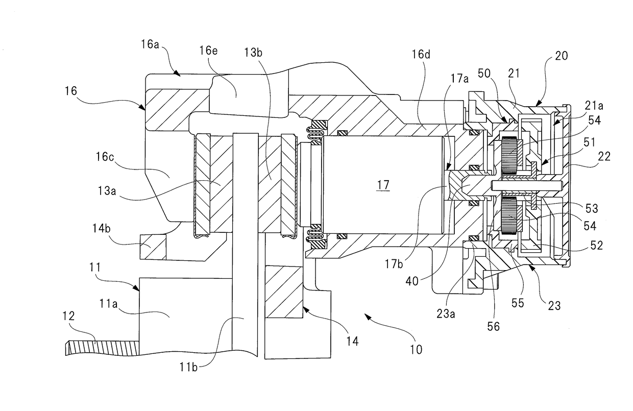
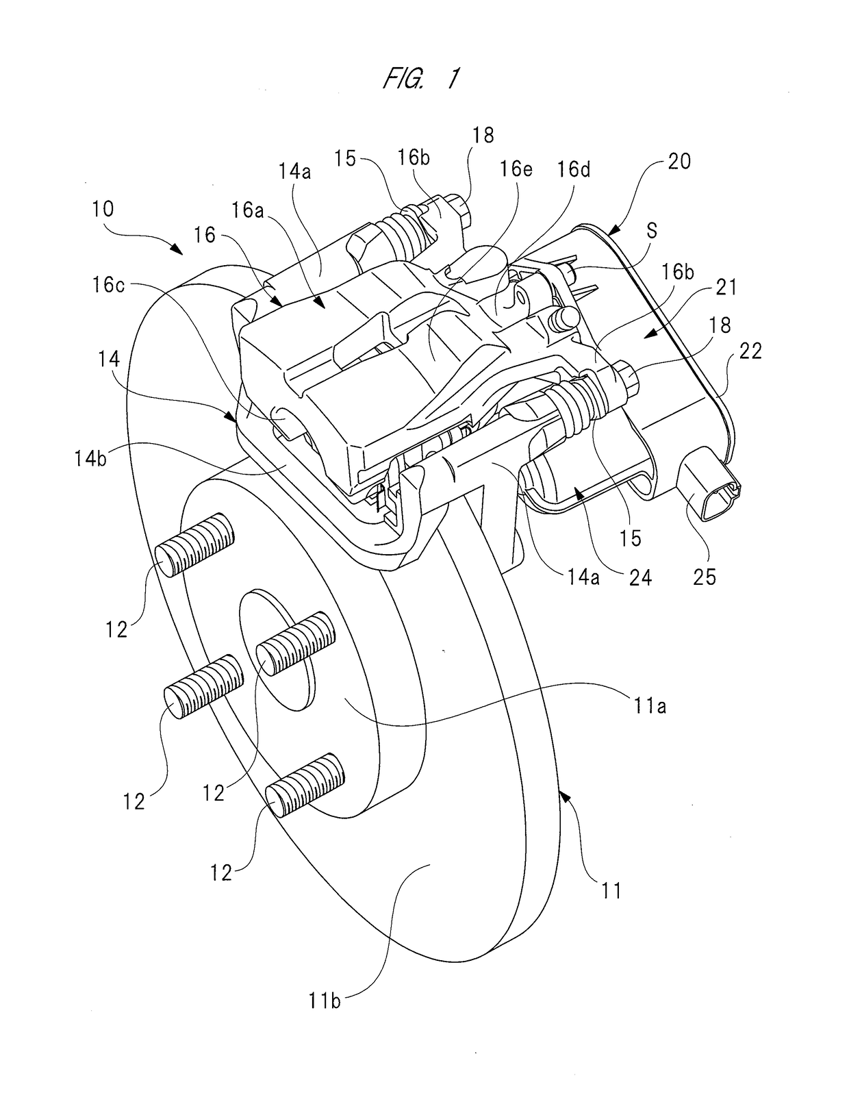
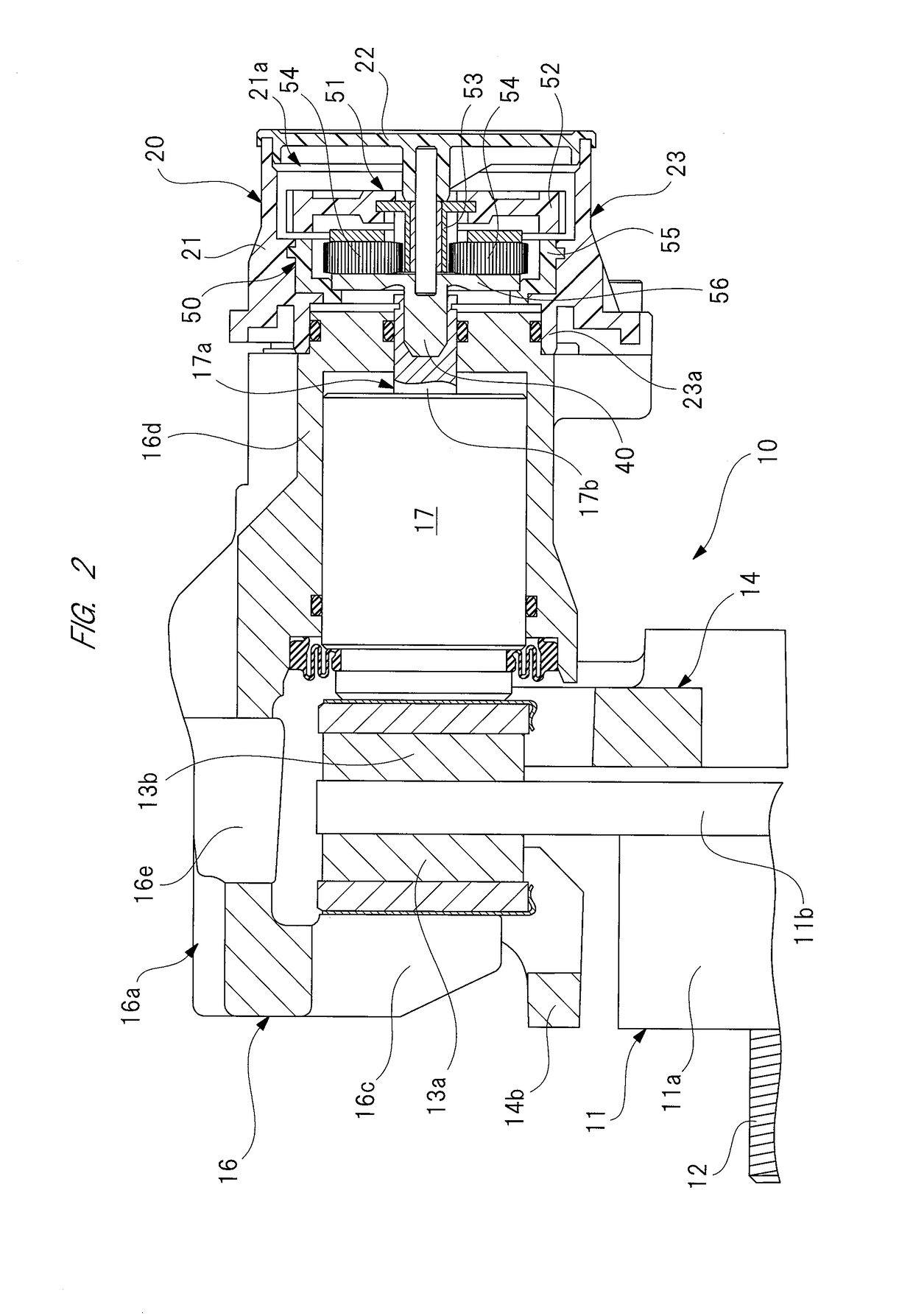
[0039]FIG. 1 is a perspective view of a general outline of a brake apparatus, FIG. 2 is a sectional view describing an internal structure of the brake apparatus, FIG. 3 is a perspective view of a case side of the actuator of the first embodiment, FIG. 4 is a perspective view of a cover side of the actuator of FIG. 3, FIG. 5 is a sectional view describing an internal structure of the actuator of FIG. 3, FIG. 6 is a side view describing a manufacturing procedure of the case of FIG. 3, FIG. 7 is a plan view describing the manufacturing procedure of the case of FIG. 3, and FIG. 8 is an enlarge view of a portion of a broken circle “A” of FIG. 7.

[0040]As shown in FIGS. 1 and 2, a brake apparatus (disk brake) 10 includes an electric parking brake apparatus, and includes a rotor 11 integrally and rotatably attached to an axel (not shown) of a vehicle. The rotor 11 includes: a rotor main body 11a havin...

second embodiment

[0108]FIG. 9 is a perspective view showing an outer appearance of a case of an actuator of a second embodiment, FIG. 10 is a perspective view showing the inside of the case of FIG. 9, FIG. 11 is a view along an arrow “B” of FIG. 9, FIG. 12 is a sectional view along a longitudinal direction of the case of FIG. 9, FIG. 13 is a sectional view along a C-C line of FIG. 11, FIG. 14 is a sectional view along a D-D line of FIG. 11, FIG. 15 is a side view describing a manufacturing procedure of the case of FIG. 9, and FIG. 16 is a partially enlarged plan view describing the manufacturing procedure of the case of FIG. 9.

[0109]An actuator of the second embodiment is different from the actuator 20 of the first embodiment (refer to FIG. 3) only in the structure of a case 100 and the shape of a cover (not shown) hermetically closing an opening 101 of the case 100. The cover of the actuator of the second embodiment has the same functions as those of the cover 22 of the first embodiment (refer to F...


PUM

PropertyMeasurementUnit
speedaaaaaaaaaa
lengthaaaaaaaaaa
shapeaaaaaaaaaa

Abstract

Since a second reinforcing rib (24e) protruding from a motor accommodating portion (24) to outside is provided to a portion formed with a weld line (WL) formed by the merger of molten resin (MR), the material thickness of the portion formed with the weld line (WL) can be increased. Therefore, the strength of the portion formed with the weld line (WL) is improved, and the strength of a case (21) as a whole can be improved. The case (21) sufficiently resistible to outer shocks can be achieved, and can be sufficiently used even in adverse environments such as a place near an undercarriage of a vehicle, and high reliability can be obtained. Since a small flange portion is provided on a caliper fixing portion side which supports an output shaft where large running torque is loaded, the weld line can be kept away from the caliper fixing portion, with this small flange portion taken as an inlet portion for the molten resin. Thus, with the caliper fixing portion side of the case inhibited from being distorted, it is possible to reliably inhibit unusual noise and so forth from occurring from an actuator.

Description

CROSS-REFERENCE TO RELATED APPLICATIONS[0001]This application is a National Stage application of International Patent Application No. PCT / JP2016 / 053444, filed on Feb. 5, 2016, which claims priority to Japanese Patent Application No. 2015-025285, filed on Feb. 12, 2015, each of which is hereby incorporated by reference in its entirety.TECHNICAL FIELD[0002]The present invention relates to an actuator which includes: a motor having a rotation shaft; an output shaft for outputting rotation of the rotation shaft; a speed reduction mechanism provided between the rotation shaft and the output shaft, and a case in which the motor, the output shaft, and the speed reduction mechanism are accommodated, and relates to a method of manufacturing the actuator.BACKGROUND ART[0003]Conventionally, an in-vehicle actuator mounted on a vehicle such as an automotive vehicle is used as, for example, a driving source for power window apparatus or sliding door opening / closing apparatus. Since this actuator ...

Claims


Application Information

Patent Timeline
Patent Type & Authority Applications(United States)
IPC IPC(8): F16H57/021B60T13/74H02K5/08H02K15/14H02K7/116F16H57/03B29C45/00
CPCF16H57/021F16H57/03B60T13/746B29C45/0046H02K15/14H02K7/116H02K5/08F16H2057/02034B60T1/065B29K2067/006B29C2045/0049F16D2131/00
Inventor AIDA, SATOSHI
Owner AKEBONO BRAKE IND CO LTD
Learn More