
Constellation Configuration for Constellations having a Large Number of LEO Satellites

a constellation and constellation technology, applied in the field of constellations, can solve the problems of increasing the path loss of rf transmission, increasing the launch and transfer cost, and exceedingly difficult constellation design, and achieve the effect of increasing the level of passive safety

Active Publication Date: 2018-01-25
WORLDVU SATELLITES
View PDF18 Cites 50 Cited by
  • Summary
  • Abstract
  • Description
  • Claims
  • Application Information

AI Technical Summary

Benefits of technology

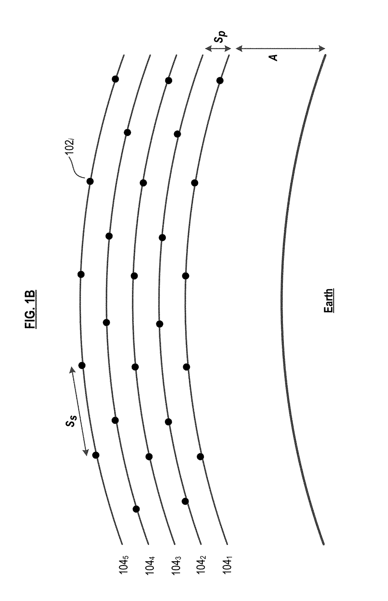
The present invention provides a constellation configuration that is particularly useful for large constellations with at least 100 satellites. Unlike previous designs, the satellites are segregated into "planes," with each plane having an equal number of satellites and flown at a different altitude. This configuration provides higher levels of passive safety within the constellation compared to conventional designs where all satellites are at substantially the same altitude. The inventor initially considered a configuration where all satellites were at the same altitude, but this was not optimal for the payload footprint on the ground. A design change in the payload resulted in a change to the footprint, from circular to rectangular, which eliminated the need to maintain satellites in adjacent planes in a constant relative in-track position.

Problems solved by technology

Quite to the contrary, the essentially infinite number of choices for the six Keplerian orbital parameters makes the design of a satellite constellation an exceedingly difficult problem.
Increasing the altitude increases the coverage of each satellite in the constellation thereby decreasing the number of satellites required, but it also increases launch and transfer costs.
It also increases path losses for RF transmissions and increases communications latency.
An increase in RF power is required to compensate for the increased path losses, as is a concomitant increase in the size of the hardware that is required to provide the increased power.
Ultimately, this requires an increase in the size and the cost of the satellites.
In addition to loss or compromise of the mission, a collision between constellation satellites or other satellites generates space debris.
Such debris becomes an ever-present risk to other satellites, particularly those remaining in the constellation in which the collision occurred, since any debris generated may remain in the vicinity of the constellation for a long time.
As the number of satellites in a constellation increases, so does the complexity of the collision-avoidance problem.
Furthermore, it might not be possible to maintain even spacing between satellites in each plane, which is required by the payloads to provide even ground coverage (discussed further below).
Maintaining such spacing would be very problematic for large constellations if all the satellites were at the same altitude.
Having different numbers of satellites in each plane, at the same altitude, requiring them to be evenly spaced, and requiring that they maintain reasonable distances from each other, creates an unworkable problem.
That is, an uncontrolled satellite in one plane will not intersect the altitude of other planes for several years, providing more than adequate time to adjust the constellation and avoid potential collisions.
Potential drawbacks of the multi-altitude configuration are that:The insertion and removal of satellites in the constellation is relatively more complex than for conventional configurations.
500 meters), the complexity is significantly reduced.Also, there is a potential for an increase in telemetry, tracking, and command (“TT&C) co-channel interference occurrences.Satellites in different planes (i.e., different altitudes) will have different fields-of-view and different path losses.
As a consequence of the potential drawbacks, in addition to any other considerations, the multi-altitude configuration might not be suitable for all types of missions.
Such motion would not be desirable for constellations that have payload footprints that interlock.
This also complicates (but not necessarily precludes) the use of inter-satellite links within the constellation.

Method used


Image

  • Constellation Configuration for Constellations having a Large Number of LEO Satellites
  • Constellation Configuration for Constellations having a Large Number of LEO Satellites
  • Constellation Configuration for Constellations having a Large Number of LEO Satellites

Examples


Embodiment Construction

[0031]Those skilled in the art will appreciate that the term “altitude” is referenced to the ground, which changes in radius from the center of the Earth by up to about 30 km depending on surface location. Orbits are ellipses with a narrowest part (minor axis) and a widest part (major axis) through the center; the semi-major axis is half of the major axis and describes the average height of an orbit. For simplicity, the term “altitude” is used in this disclosure in instances in which it might be more appropriate to reference “SMA;” those skilled in the art will recognize those instances and understand the distinction.

[0032]FIGS. 1A and 1B depict satellite constellation 100 in accordance with the illustrative embodiment of the present invention. In the illustrative embodiment, satellite constellation 100 provides internet connectivity to a plurality of users, which can be residential or business users. Constellation 100 includes a plurality of satellites 102i where i=1, m (collective...


PUM


Abstract

A configuration for a satellite constellation has a plurality of planes, each plane including a plurality of satellites therein, at least some of the planes situated at a different altitude than other of the planes. In some embodiments, all planes contain the same number of satellites; in some other embodiments, at least one plane includes a different number of satellites than the other planes in the constellation. In some embodiments, the satellites in each plane are evenly spaced.

Description

FIELD OF THE INVENTION[0001]The invention pertains generally to satellites and more particularly to a constellation design.BACKGROUND OF THE INVENTION[0002]Artificial satellites (hereinafter after “satellites”) are used for telecommunications, navigation, disaster monitoring, weather monitoring / forecasting, astronomical observations, and intelligence gathering, to name but a few of their many important functions. A satellite constellation is a group of satellites working in concert under shared control. Their synchronized behavior provides significant improvements, relative to a lone satellite, in temporal and spatial coverage. The first constellation to be used operationally—TRANSIT—was deployed in the early 1960s by the US Navy.[0003]Satellite constellation design is often viewed, mistakenly, as the simple process of placing multiple copies of a single satellite in modified orbits. Quite to the contrary, the essentially infinite number of choices for the six Keplerian orbital para...

Claims


Application Information

Patent Timeline
IPC IPC(8): B64G1/10
CPCB64G1/1007B64G1/1085B64G1/242H04B7/185B64G1/1014B64G1/1021H04B7/195H04B7/18513
Inventor MEEK, MATTHEW CAMERON
Owner WORLDVU SATELLITES
Learn More