Hybrid vehicle

a hybrid vehicle and engine technology, applied in the direction of engine-driven generators, transportation and packaging, etc., can solve the problems of high engine operation efficiency, low engine efficiency, tooth contact noise, etc., to reduce the output torque reduce the effect of unnecessary increase in the rotation speed of the internal combustion engin

Active Publication Date: 2018-01-25
TOYOTA JIDOSHA KK
View PDF0 Cites 12 Cited by
  • Summary
  • Abstract
  • Description
  • Claims
  • Application Information

AI Technical Summary

Benefits of technology

[0016]With the thus configured hybrid vehicle, because it is possible to switch the clutch into the engaged state after synchronization of the first rotation speed with the second rotation speed has completed, it is possible to smoothly switch from the series-parallel mode to the series mode.
[0017]The controller may be configured to, at the time of switching from the series-parallel mode to the series mode, place the power transmission unit in the neutral state, and reduce an output torque of the internal combustion engine. With the thus configured hybrid vehicle, it is possible to suppress an unnecessary increase in the rotation speed of the internal combustion engine.
[0018]With the above-described hybrid vehicle, at the time of switching from the series-parallel mode to the series mode, after the power transmission unit is controlled such that the power transmission unit is placed in the neutral state, the first rotary electric machine is controlled such that the first rotation speed and the second rotation speed are synchronous with each other. Therefore, it is possible to switch the clutch into the engaged state in a state where the first rotation speed and the second rotation speed are synchronous with each other. Therefore, it is possible to provide the hybrid vehicle that smoothly switches from the series-parallel mode to the series mode.

Problems solved by technology

In the series-parallel hybrid system, there is a concern that tooth contact noise occurs in a gear mechanism provided in a drive system between the engine and the drive wheels because of torque fluctuations of the engine at a low vehicle speed, or the like, so it is required to select an operating point of the engine such that tooth contact noise does not occur, and the engine may be operated at an operating point at which fuel consumption is not optimal.
However, the entire torque of the engine is once converted to electric power and then the electric power is converted back to the torque of the drive wheels with the motor, so the series hybrid system is inferior in fuel consumption in a speed range in which the operation efficiency of the engine is high to the series-parallel hybrid system.
As a result, switching to the series mode may be delayed.

Method used


Image

  • Hybrid vehicle
  • Hybrid vehicle
  • Hybrid vehicle

Examples


Embodiment Construction

[0040]Hereinafter, an embodiment of the invention will be described with reference to the accompanying drawings. Like reference numerals denote the same or corresponding portions in the following embodiment, and the description thereof will not be repeated.

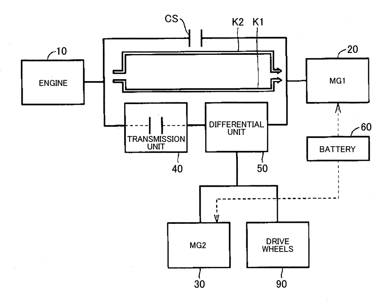
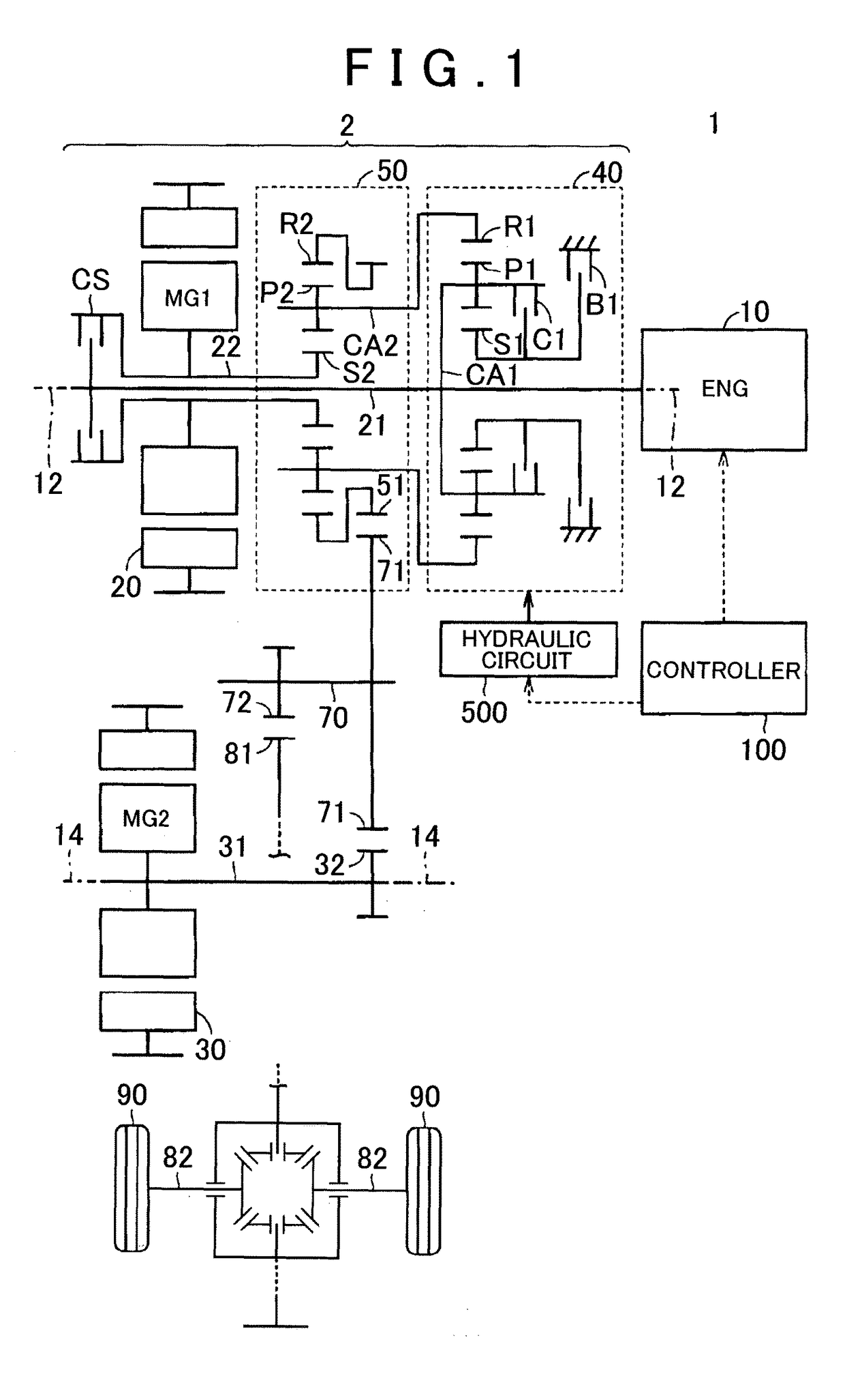
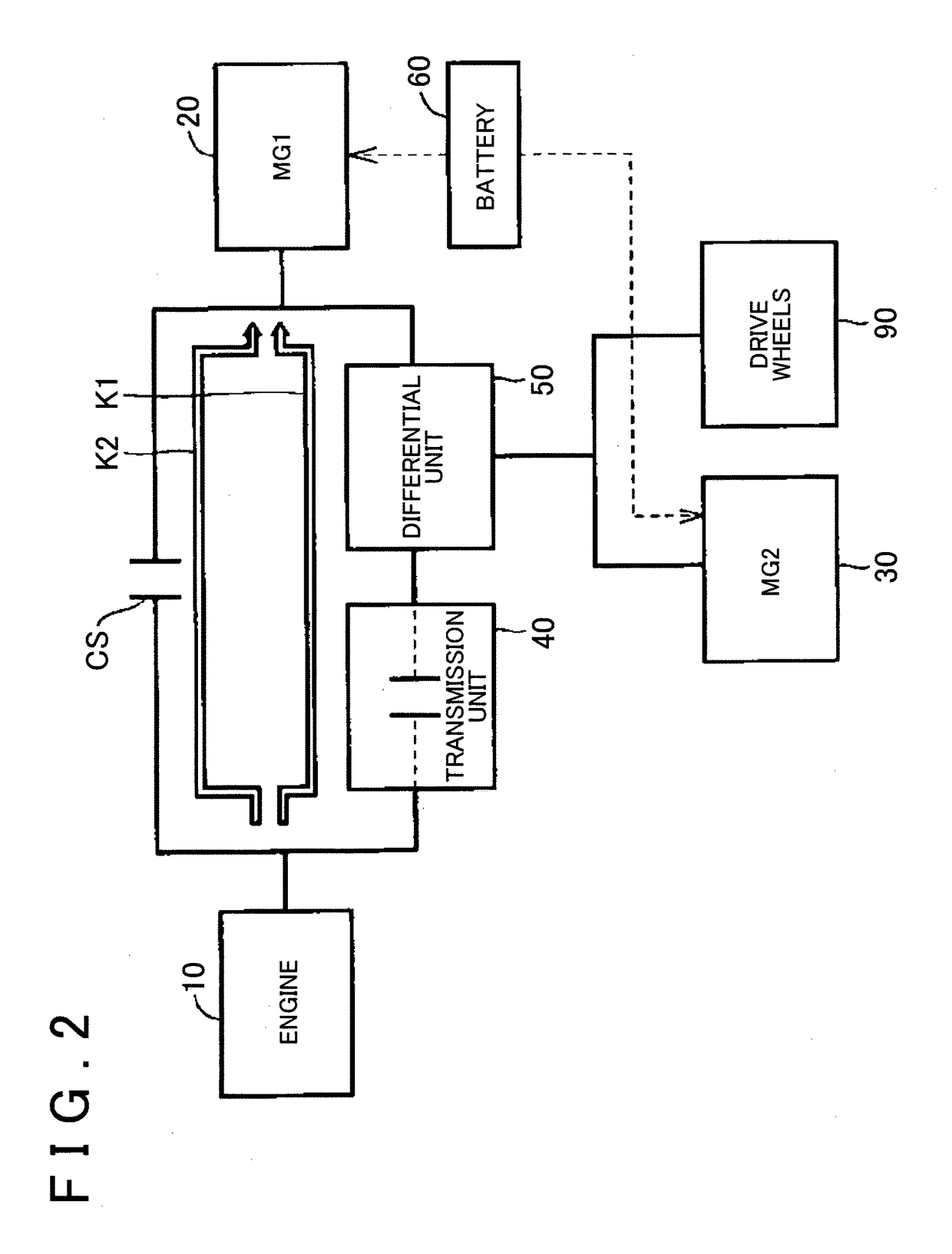
[0041]FIG. 1 is a view that shows the overall configuration of a hybrid vehicle including a drive system according to the embodiment of the invention.

[0042]As shown in FIG. 1, the hybrid vehicle 1 (hereinafter, also referred to as vehicle 1) includes an engine 10, the drive system 2, drive wheels 90 and a controller 100. The drive system 2 includes a first motor generator (hereinafter, referred to as first MG) 20 that is a first rotary electric machine, a second motor generator (hereinafter, referred to as second MG) 30 that is a second rotary electric machine, a transmission unit 40, a differential unit 50, a clutch CS, an input shaft 21, a counter shaft 70 that is an output shaft of the drive system 2, a differential gear set 80...


PUM


Abstract

A control process including the following steps is executed. The control process includes, at the time of switching from series-parallel mode to series mode, a step of reducing an engine torque, a step of releasing a clutch, a step of reducing a reaction torque of a first rotary electric machine and a step of increasing a torque of a second rotary electric machine, and, when synchronization is started and a step of increasing a positive torque of the first MG, a step of starting engagement of a clutch, and, when a rotation speed of the first rotary electric machine and a rotation speed of an engine are synchronous with each other, a step of engaging the clutch.

Description

BACKGROUND OF THE INVENTION1. Field of the Invention[0001]The invention relates to a hybrid vehicle and, more particularly, to a hybrid vehicle including first and second rotary electric machines and a transmission unit.2. Description of Related Art[0002]There is known a hybrid vehicle including not only an engine, two rotary electric machines and a power split mechanism but also a transmission mechanism between the engine and the power split mechanism.[0003]A hybrid vehicle described in International Application Publication No. 2013 / 114594 employs a series-parallel hybrid system. In the vehicle having a series-parallel hybrid system, the power of an engine is transmitted to a first rotary electric machine (first motor generator) and is used to generate electric power, while part of the power of the engine is also transmitted to drive wheels via a power split mechanism.[0004]There is also known a hybrid vehicle having a configuration (series hybrid system) by which the hybrid vehicl...

Claims


Application Information

Patent Timeline
Patent Type & Authority Applications(United States)
IPC IPC(8): B60W20/20B60W10/06B60K6/445B60W20/40B60K6/387B60K6/442B60W10/02B60W10/08B60L50/16
CPCB60W20/20B60W10/02B60W10/06B60W10/08B60W20/40B60K6/387B60K6/442B60K6/445B60W2710/0666B60W2710/021B60K6/365B60Y2300/42B60Y2300/80B60Y2300/182Y10S903/93F16H2200/2007Y10S903/911F16H3/728B60K6/543Y10S903/918B60K2006/381B60W20/00F16H2037/0873F16H2200/2038Y02T10/62
Inventor TAKAGI, KIYONORIBANSHOYA, HIDEHIKOKAWAMOTO, ATSUSHISUZUKI, HARUHISAIMAMURA, TATSUYAKANADA, TOSHIKITABATA, ATSUSHI
Owner TOYOTA JIDOSHA KK
Why Eureka
Try Eureka