System and method for operating a subsea sensor field

a sensor field and subsea technology, applied in underwater equipment, special-purpose vessels, instruments, etc., can solve the problems of affecting marine life, high cost of operation, and inability to collect data, so as to facilitate the autonomous operation of the auv, eliminate the need for communication links, and improve the effect of accuracy

Active Publication Date: 2018-01-18
OCTIO
View PDF2 Cites 0 Cited by
  • Summary
  • Abstract
  • Description
  • Claims
  • Application Information

AI Technical Summary

Benefits of technology

[0020]In a preferred embodiment, the AUV comprises a control system and a set of base units comprise a corresponding guidance system, such that the AUV can operate without communication to the surface except through the docking station. The set of base units provide a set of fixed locations suitable for a position system, e.g. one based on acoustic waves or radio waves. In many instances, a commercially available acoustic positioning system would be suitable. However, any alternative known in the art may be considered, for example a visual beacon, an acoustic beacon or a guidance system based on a Hall-sensor tracking a conducting wire. Either way, navigation and localisation of a base unit is faster and more accurate using such a guidance system than by using inertial navigation means only. The AUV can obviously contain a battery unit, and instructions, including software and firmware updates, can be provided through the docking station. Thus, the AUV can be operated without separate power lines and communication lines, and without a dedicated operator steering the AUV by remote control. In general, a guidance system facilitates autonomous operation of the AUV, thereby eliminating the need for a communication link from the AUV to the surface and reducing the need for a dedicated human operator at the surface.

Problems solved by technology

A disadvantage is that the collected data include P-waves (primary pressure waves) only, as S-waves (secondary shear waves) from a subterranean structure do not propagate through the water column to the hydrophones in the streamers.
However, such vessels typically must be hired a long time in advance, and their cost of operation is relatively high.
Other disadvantages are problems associated with towing and releasing powerful acoustic sources near an installation, adverse effects on marine life, etc.
As known in the art, deploying components on the seafloor with an ROV is time consuming and / or inaccurate.
This is a disadvantage in time-lapse monitoring, where the sensors should preferably be located at the same spot before and after retrieval and redeployment.

Method used


Image

  • System and method for operating a subsea sensor field
  • System and method for operating a subsea sensor field

Examples


Embodiment Construction

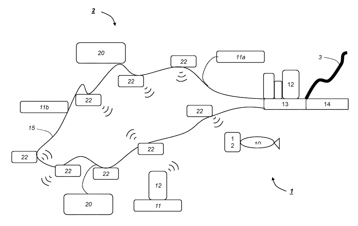
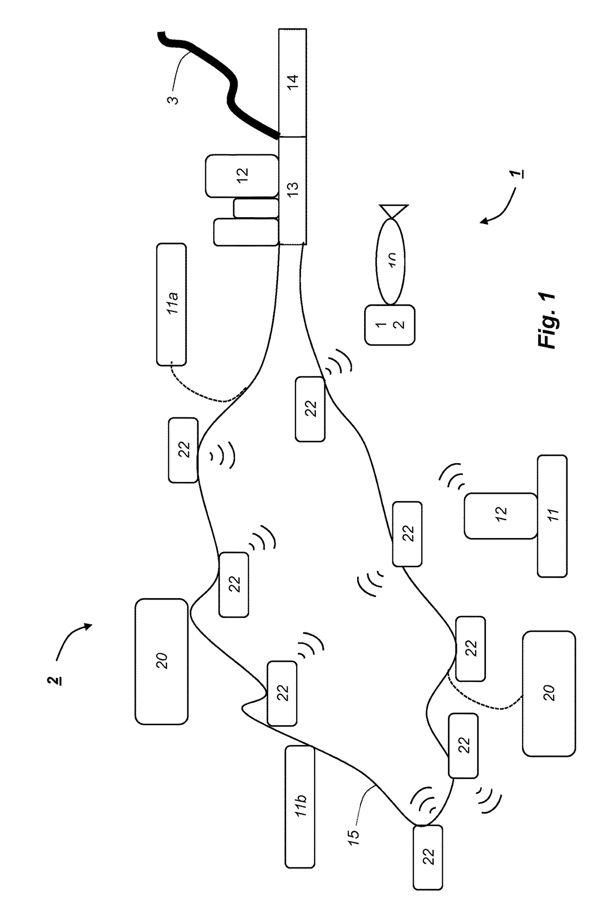
[0028]FIG. 1 illustrates a sensor field 2 deployed on a seafloor, i.e. under a body of water. The sensor field 2 has permanent sources 20 and sensors 22 of various kinds as described in the introduction. The permanent sources 20 and sensors 22 are connected to a wired network 15, which provides electric power and / or communication links. The sensor field 2 could be designed differently than shown in FIG. 1, for example as a rectangular grid of synthetic ropes with an autonomous node at each intersection. The grid could be made of synthetic rope or steel wire for maintaining predetermined distances. Thus, a grid does not imply power supply or communication, but power and / or communication can be provided through a grid.

[0029]The sensor field 2 is operated by a system 1 comprising an AUV 10, base units 11, 11a, 11b, control units 12, a service station 13 for the control units 12 and a docking station 14 for the AUV 10.

[0030]When connected, a base unit 11 and a control unit 12 correspond...


PUM


Abstract

A system (1) for operating a subsea sensor field (2), comprises an automated underwater vehicle—AUV (10) and a subsea service station (13). A sensor (11, 12) in the sensor field (2) comprises a permanently installed base unit (11) and a removable control unit (12). The AUV (10) moves control units (12) to the service station (13) for charging and updating, and then back to the base units. The permanent positions of the base units (11) facilitate time-lapse surveys, and saves energy as heavy equipment may remain on the seafloor.

Description

BACKGROUNDField of the Invention[0001]The present invention concerns a system and method for operating a subsea sensor field, i.e. an array of sensors and sources for monitoring a region of interest.Prior and Related Art[0002]Subsea reservoirs or geological structures may be monitored using different time-lapse techniques, each having its advantages and disadvantages. A first type of technique involves repeated marine seismic surveys with various types of surface-towed seismic equipment, i.e. powerful acoustic sources and associated seismic streamers. The main advantage of these techniques is an ability to monitor or survey large areas relatively fast. A disadvantage is that the collected data include P-waves (primary pressure waves) only, as S-waves (secondary shear waves) from a subterranean structure do not propagate through the water column to the hydrophones in the streamers.[0003]A second technique involves repeated marine seismic surveys with re-deployable ocean bottom sensor...

Claims


Application Information

Patent Timeline
Patent Type & Authority Applications(United States)
IPC IPC(8): G01V1/38G01V1/20B63C11/52B63G8/00
CPCG01V1/3852G01V1/202B63G8/001B63C11/52B63G2008/007B63G2008/008G01V1/3843G01V1/166G01V1/38G01V13/00
Inventor LOVHEIM, LEONFAGER S, BJARTE EVENOLDERVOLL, MAGNEBRANDSAETER, HELGE
Owner OCTIO
Why Eureka
Try Eureka