
Dynamic stabilizer for solar trackers

a technology of dynamic stabilizer and tracker, which is applied in the safety of solar heat collectors, shock absorbers, lighting and heating equipment, etc., can solve the problems of limiting the practical length of the row, affecting the use of dampers, and affecting the stability of the tracker, so as to increase the structural capacity of the structure, increase the stiffness and natural frequency of the structure, the effect of increasing the structural capacity

Active Publication Date: 2018-01-11
COROSOLAR LLC
View PDF7 Cites 41 Cited by
  • Summary
  • Abstract
  • Description
  • Claims
  • Application Information

AI Technical Summary

Benefits of technology

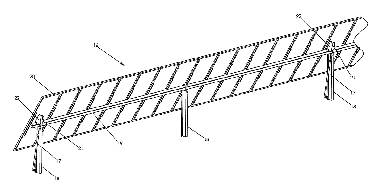
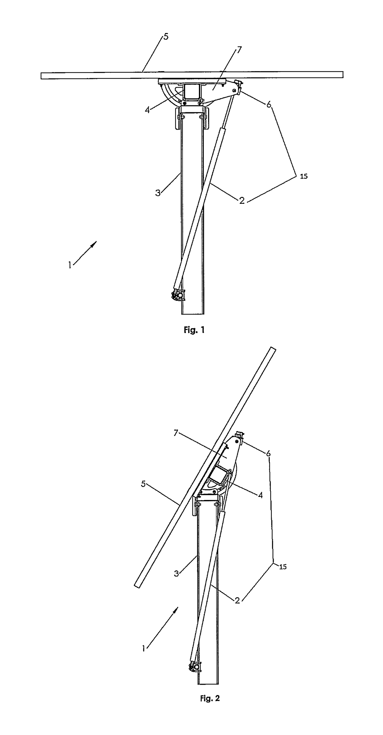
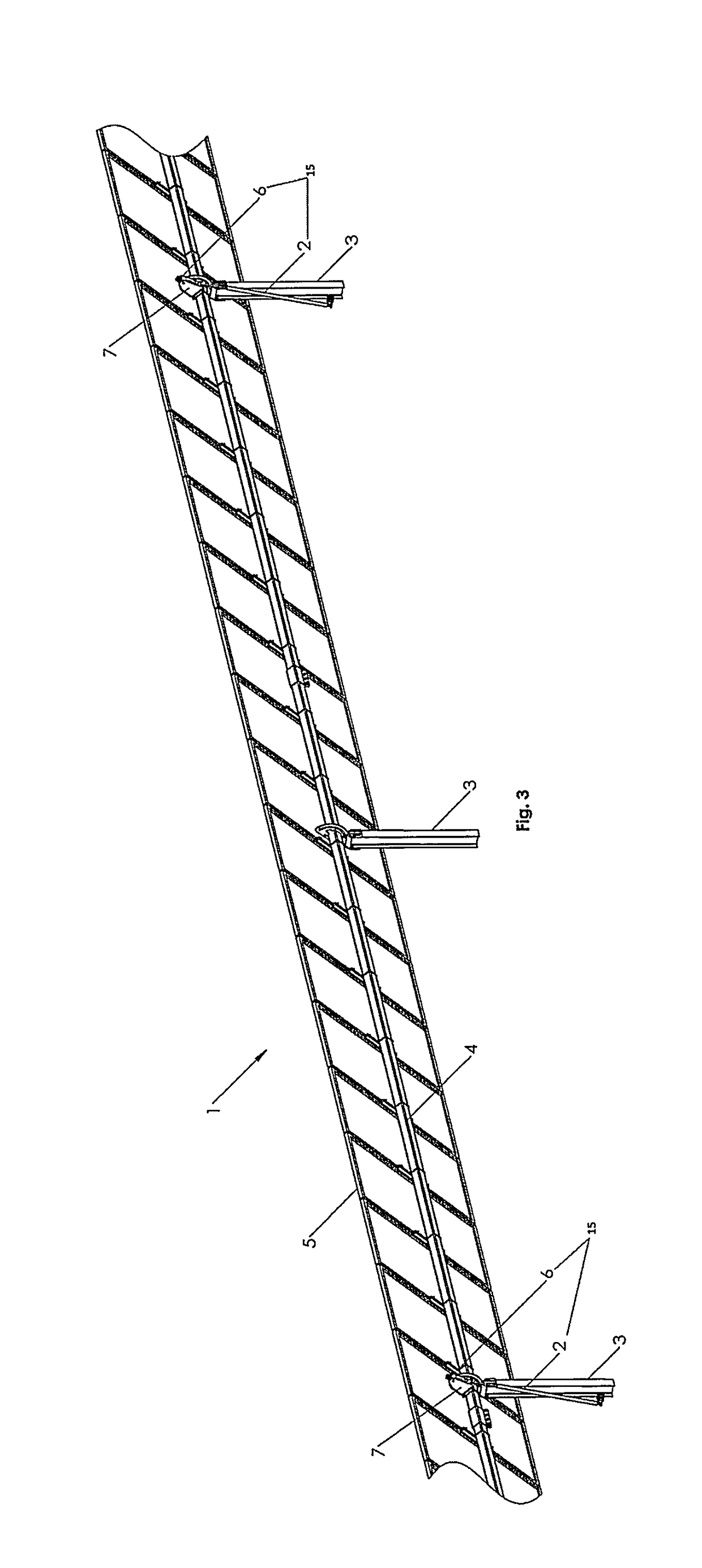
The present invention introduces a non-drive dynamic stabilizer that includes a damper and an actuator, which offers multiple states of support to a solar tracker structure. This dynamic stabilizer serves to redistribute loads, increase stiffness and natural frequency of the structure, and increase its capacity. The dynamic stabilizer is actuated by a control system in real-time based on the demands on the structure. Overall, the invention provides better stability and resilience to the solar tracker structure, ensuring its optimal performance.

Problems solved by technology

With such a design, however, the modules being moved can be a significant distance (e.g. 150 ft) from the actuator.
However, not having a torque tube to efficiently transmit torque to the center of the row appears to limit the practical length of the row.
Dampers, however, are of questionable use when designing for critical environmental events per generally accepted civil engineering standards, e.g. ASCE 7-10.
Because dampers can move, they do not necessarily increase the rated or design static load capacity of the structure, nor do they necessarily increase the static stiffness of the structure.

Method used


Image

  • Dynamic stabilizer for solar trackers
  • Dynamic stabilizer for solar trackers
  • Dynamic stabilizer for solar trackers

Examples


Embodiment Construction

[0026]The following description is provided to enable any person skilled in the art to make and use the invention and sets forth the best modes contemplated by the inventor for carrying out the invention. Various modifications, however, will remain readily apparent to those skilled in the art. Any and all such modifications, equivalents and alternatives are intended to fall within the spirit and scope of the present invention.

[0027]In general, the present invention is a non-drive device that provides multiple states of support to a solar structure. These states may include 1) flexible movement and / or damping during normal operation (i.e. tracking) and / or 2) rigid or locked, whereby the dynamic stabilizer acts as a restraint. The dynamic stabilizer serves to 1) redistribute the loads; 2) increase the stiffness and natural frequency of the structure; and 3) increase the structural capacity of the structure. The dynamic stabilizer is actuated by a control system according to the real-t...


PUM


Abstract

A non-drive dynamic stabilizer includes a damper and an actuator. The dynamic stabilizer provides multiple states of support to a solar tracker structure. These states may include 1) flexible movement and / or damping during normal operation (i.e. tracking) and / or 2) rigid or locked, whereby the dynamic stabilizer acts as a restraint. The dynamic stabilizer is actuated by a control system according to the real-time demands on the structure. Sensors to provide input to the control system may include wind speed sensors, wind direction sensors, snow sensors, vibration sensors and / or displacement sensors.

Description

[0001]This application claims the benefit of U.S. Provisional Application No. 62 / 360,289, filed Jul. 8, 2016, entitled LOCKING MECHANISM FOR SOLAR TRACKERS, the disclosure of which is herein incorporated by reference.BACKGROUND OF THE INVENTION1. Field of the Invention[0002]The present invention relates to solar tracking systems, and more particularly, to a dynamic stabilizer system for resisting environmental forces acting on a solar tracking system.2. Description of the Related Art[0003]Solar trackers have moving and fixed parts. The fixed parts include the foundations and bearing assemblies. The moving parts include elements such as solar modules, torque tubes, levers, linkages, and other hardware. An actuator is required to move the moving parts. The actuator positions the solar modules so that they generate more electricity than a fixed-tilt system. During adverse environmental conditions, such as high winds, the actuator can be used to place the system into “stow,” a position ...

Claims


Application Information

Patent Timeline
IPC IPC(8): H02S20/32F24J2/46F24J2/54F24J2/52F16F9/56F16F9/19
CPCH02S20/32F24J2/4638F24J2/5262F16F9/19F16F9/56F24J2002/5288F24J2002/5496F24J2/5427F24S30/425F24S25/10F24S50/60F24S2030/11F24S40/85F24S2030/19Y02E10/47F24S25/67F24S30/458F24S2025/018
Inventor CHILDRESS, ISAACWARD, ROBKEELIN, PATRICKBUSBY, LAURENMAULICK, MICHAEL
Owner COROSOLAR LLC
Learn More