Switched reluctance motor and method therefore

a technology of resistive motor and resistive motor, which is applied in the direction of electronic commutation motor control, synchronous motors, rotating magnets, etc., can solve the problems of less time available for current to build up and large induced torque, and achieves increased counter-electromotive force, large induced torque, and rapid torque drop

Inactive Publication Date: 2018-01-04
PUNCH POWERTRAIN NV
View PDF1 Cites 5 Cited by
  • Summary
  • Abstract
  • Description
  • Claims
  • Application Information

AI Technical Summary

Benefits of technology

The present invention is a switched reluctance motor that can adjust its behavior at different speeds of the rotor by switching the coils in different configurations. This switching is done automatically based on the speed of the rotor, which allows for optimal torque at both low and high speeds. The motor can also be manually switched between different configurations, such as for different operational conditions. The switches used can be mechanical or electrical, with the choice depending on the desired speed and cost-effectiveness. The motor can also be used in an automatic transmission system that changes gear based on the speed of the rotor, improving overall efficiency.

Problems solved by technology

Therefore, strong magnetic fields are generated in these coils giving rise to a large induced torque.
Shorter commutation periods due to higher rotational velocity result in less time available for the current to build up.

Method used


Image

  • Switched reluctance motor and method therefore
  • Switched reluctance motor and method therefore
  • Switched reluctance motor and method therefore

Examples


Embodiment Construction

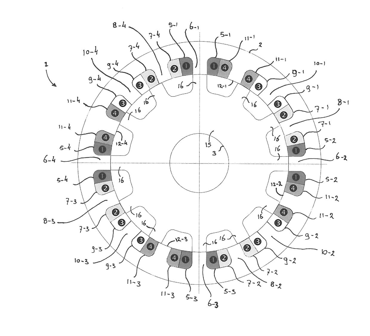
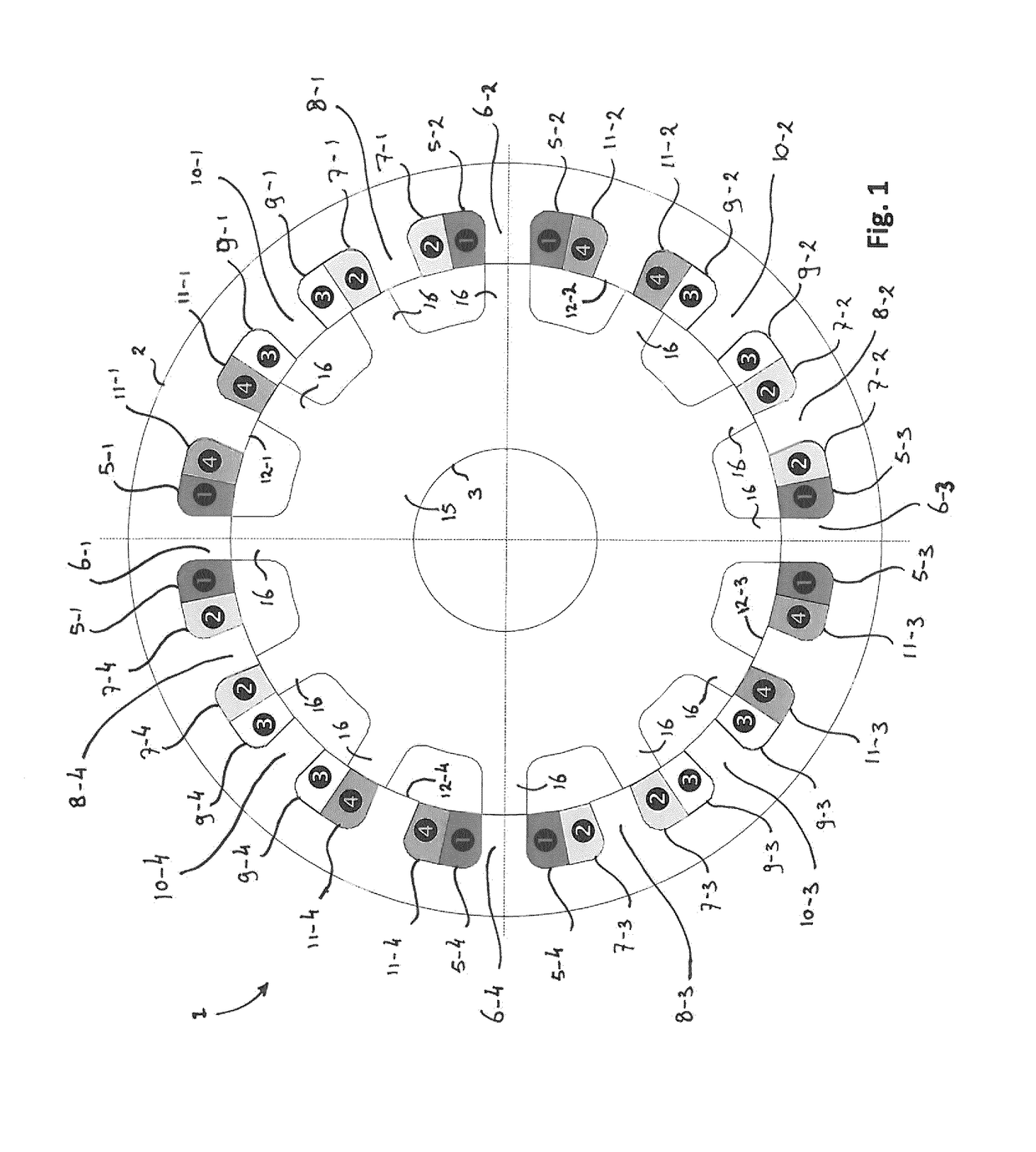
[0039]The figures include a large number of reference signs indicating various components, parts and / or aspects of the embodiments that are schematically illustrated. In addition, reference is made to various phase stages by referring to a phase stage number illustrated as a black dot with a number, i.e. phase stages , , , and . These phase stage numbers are not to be mistaken for the reference numerals (which include for example the motor 1, the stator 2 or the rotor 3). Therefore, the notation of the phase stage numbers , , , and is used accordingly in the description to identify the phase stages, whereas the reference numerals to the motor, stator and rotor are provided as regular numbers.

[0040]FIG. 1 schematically illustrates a switched reluctance motor in accordance with the present invention. The switched reluctance motor 1 comprises a stator 2 and a rotor 3. The rotor 3 is rotatable with respect to the stator 2, for example by suspending the rotor 3 using suitable bearings (...


PUM


Abstract

The invention involves a switched reluctance motor, comprising a stator and a rotor rotatable relative to the stator. The stator comprises several circumferentially arranged coils and stator poles, the stator poles forming the cores of the coils. The rotor comprises several counter poles for interacting with the stator poles for applying a reluctance torque on the rotor. The motor comprises phase inputs for receiving an actuation signal for actuating one or more phase stages. Each stator coil is associated with a phase stage, such that each phase stage comprises at least two coils. Each phase stage comprises a circuit stage including a switching arrangement comprising switches for selectively switching the coils of said phase stage in either one of a parallel, a serial, or a parallel-serial electrical configuration.

Description

FIELD OF THE INVENTION[0001]The present invention is directed at a switched reluctance motor, comprising a stator and a rotor, the rotor being rotatable relative to the stator, wherein the stator comprises a plurality of coils and stator poles arranged circumferentially around the rotor, the stator poles forming the cores of the coils, and wherein the rotor comprises a plurality of counter poles for interacting with the stator poles of the stator for applying a reluctance torque on the rotor, wherein the motor comprises one or more phase inputs for receiving an actuation signal for actuating a respective phase stage of one or more phase stages of the motor. The invention is further directed at an apparatus including such a switched reluctance motor, a vehicle, and a method of operating a switched reluctance motor.BACKGROUND[0002]A switched reluctance motor (SR motor) is a type of electric motor that is driven by reluctance torque on a rotor that is arranged rotatable with respect to...

Claims


Application Information

Patent Timeline
Patent Type & Authority Applications(United States)
IPC IPC(8): H02P25/18H02P9/40H02P25/086H02K19/10H02K3/28H02P25/092H02K16/04H02K21/16H02P6/182
CPCH02P25/188H02P25/086H02P25/092H02K3/28H02P9/40H02K19/103H02K16/04H02K21/16H02P6/182H02P25/08H02P25/18H02P25/0925
Inventor FAID, SAPHIR ELIASBOON, FABRICE
Owner PUNCH POWERTRAIN NV
Why Eureka
Try Eureka