Influence on Surface Interactions by Substructure Topography

Active Publication Date: 2018-01-04
NASA
View PDF5 Cites 2 Cited by
  • Summary
  • Abstract
  • Description
  • Claims
  • Application Information

AI Technical Summary

Benefits of technology

The present patent is about using adhesion prevention techniques to create aerodynamic surfaces for extreme environments such as aircraft, wind turbines and propeller blades. The technique involves using a laser to modify the surface of a substrate material to create a rough surface that prevents adhesion. This rough surface is then coated with a resin material to create a smooth surface that allows for laminar flow of air. The coating material is chosen for its low modulus of elasticity, which reduces adhesion of insect residue. This technology provides a way to protect extreme environments from adhesion and maintain smooth aerodynamic surfaces.

Problems solved by technology

This may create surface roughness that disrupts laminar flow over the aerodynamic surface.
Although laser ablation of a substrate to modify surface energy may reduce buildup of insect residue or the like on the treated surface, ice buildup on the surface may still occur (at least to some extent) due to the roughness of the treated / ablated surface.
Also, because the ablated surface is not smooth, it may interfere with laminar flow over the surface if the surface comprised of the ablated surface is utilized for an airfoil or other aerodynamic surface.

Method used


Image

  • Influence on Surface Interactions by Substructure Topography
  • Influence on Surface Interactions by Substructure Topography
  • Influence on Surface Interactions by Substructure Topography

Examples


Embodiment Construction

[0023]For purposes of description herein, the terms “upper,”“lower,”“right,”“left,”“rear,”“front,”“vertical,”“horizontal,” and derivatives thereof shall relate to the invention as oriented in FIGS. 3-5. However, it is to be understood that the invention may assume various alternative orientations and step sequences, except where expressly specified to the contrary. It is also to be understood that the specific devices and processes illustrated in the attached drawings, and described in the following specification, are simply exemplary embodiments of the inventive concepts defined in the appended claims. Hence, specific dimensions and other physical characteristics relating to the embodiments disclosed herein are not to be considered as limiting, unless the claims expressly state otherwise.

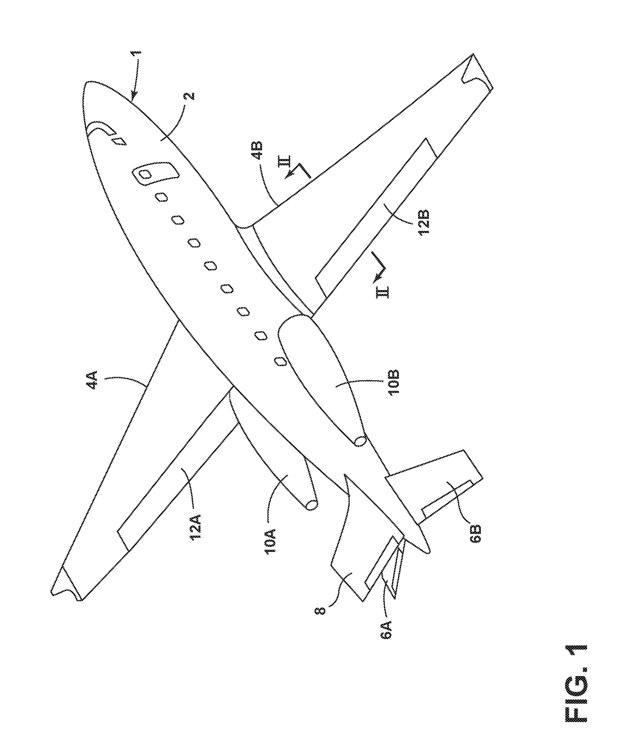
[0024]With reference to FIG. 1, an aircraft 1 includes a fuselage 2, wings 4A and 4B, horizontal stabilizers 6A and 6B, and a vertical stabilizer 8. The aircraft 1 also includes a propulsion system...


PUM

PropertyMeasurementUnit
Thicknessaaaaaaaaaa
Thicknessaaaaaaaaaa
Pressureaaaaaaaaaa

Abstract

A method of forming a smooth aerodynamic surface that permits laminar flow of air over the smooth aerodynamic surface. Selected portions of a surface of a substrate material are ablated utilizing a laser to form a treated substrate surface having a predefined roughness. The treated substrate surface is coated to form a solid layer of material having a smooth aerodynamic surface that promotes laminar flow. The solid layer of material has a lower modulus of elasticity than the substrate material to provide durotaxis when an insect impacts the solid layer of epoxy material to thereby reduce adhesion of insect residue or other matter to the smooth aerodynamic surface.

Description

CROSS-REFERENCE TO RELATED PATENT APPLICATION[0001]This patent application claims the benefit of and priority to U.S. Provisional Patent Application No. 62 / 357,430, filed on Jul. 1, 2016, the contents of which is hereby incorporated by reference in its entirety.STATEMENT REGARDING FEDERALLY SPONSORED RESEARCH OR DEVELOPMENT[0002]The invention described herein was made in the performance of work under a NASA contract and by an employee of the United States Government and is subject to the provisions of Public Law 96-517 (35 U.S.C. §202) and may be manufactured and used by or for the Government for governmental purposes without the payment of any royalties thereon or therefore. In accordance with 35 U.S.C. §202, the contractor elected not to retain title.BACKGROUND OF THE INVENTION[0003]The present disclosure relates to a method of reducing buildup of insect residue and other matter on aerodynamic surfaces. More specifically, a subsurface topography is formed utilizing laser ablation ...

Claims


Application Information

Patent Timeline
IPC IPC(8): C23C14/02C23C14/58B64C3/26B64D15/00
CPCC23C14/028B64C3/26B64D15/00C23C14/58B05D3/12B05D5/08B05D2202/25B05D2504/00B23K26/3584F01D5/288
Inventor WOHL, JR., CHRISTOPHER J.PALMIERI, FRANK L.
Owner NASA
Why Eureka
Try Eureka