Gearless drive for a rotating electrical machine

Inactive Publication Date: 2015-10-22
GE ENERGY POWER CONVERSION TECH
View PDF6 Cites 3 Cited by
  • Summary
  • Abstract
  • Description
  • Claims
  • Application Information

AI Technical Summary

Benefits of technology

[0016]The pole mounting arrangement may include a plurality of pole mounting struts which may extend in a substantially radial direction. Each pole body may be independently mounted on the rotor by at least one of said pole mounting struts. Each pole body is normally independently mounted on the rotor by at least two circumferentially spaced pole mounting struts. The use of at least two circumferentially spaced pole mounting struts may improve the stability of the pole bodies and hence the gearless drive.
[0017]Each pole mounting strut may include a length adjustment mechanism, for example a turnbuckle. The length adjustment mechanism allows the length of the pole mounting struts to be varied, and this allows the radial position of each pole body with respect to the rotor to be varied independently of the other pole bodies. This advantageously allows adjustment and optimisation of the air gap between the pole bodies and the stator.
[0018]Opposite ends of each pole mounting strut are typically secured to the pole body and the rotor by bushes. The stiffness of the bushes may be greater in the radial direction than the circumferential direction. The stiffness of the bushes may be lower in the axial direction than the radial direction. The bushes thus permit the aforesaid relative independent movement between the pole bodies and the rotor in the circumferential direction and possibly also in the axial direction, whilst minimising any purely radial movement.
[0019]The pole mounting arrangement may be arranged to permit independent movement of the pole bodies in a radially inward direction, towards the rotor, during circumferential movement of the pole bodies with respect to the rotor. More particularly, each mounting strut may be arranged to permit independent movement of its associated pole body in a radially inward direction, towards the rotor, during circumferential movement of the pole body with respect to the rotor. Each pole body may move independently about an arc whose diameter is less than the diameter of the rotor. As indicated above, any mo

Problems solved by technology

These transient loads have been known to cause fatigue damage to some of the component parts of the rot

Method used


Image

  • Gearless drive for a rotating electrical machine
  • Gearless drive for a rotating electrical machine
  • Gearless drive for a rotating electrical machine

Examples


Example

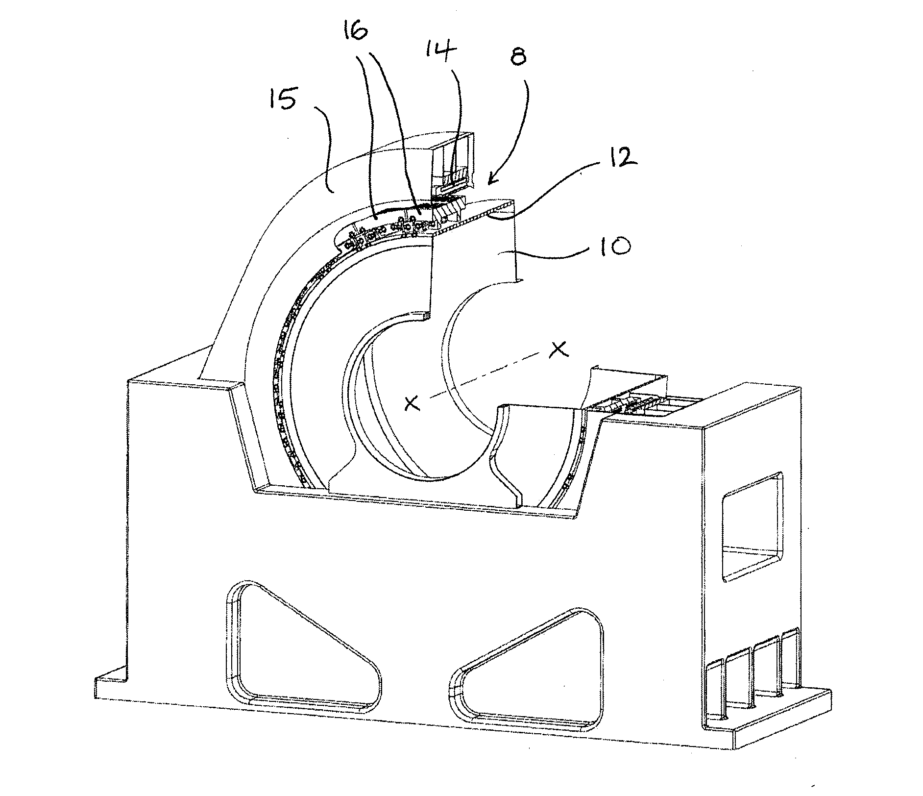
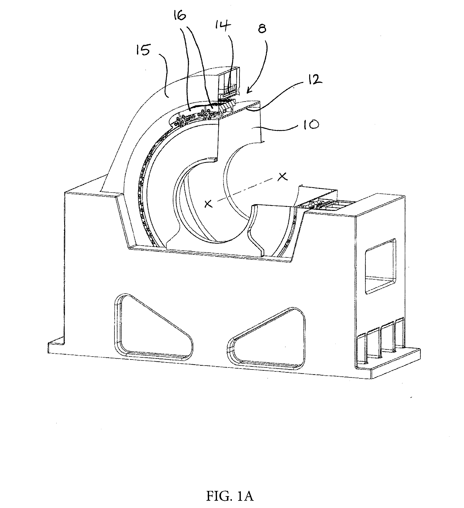
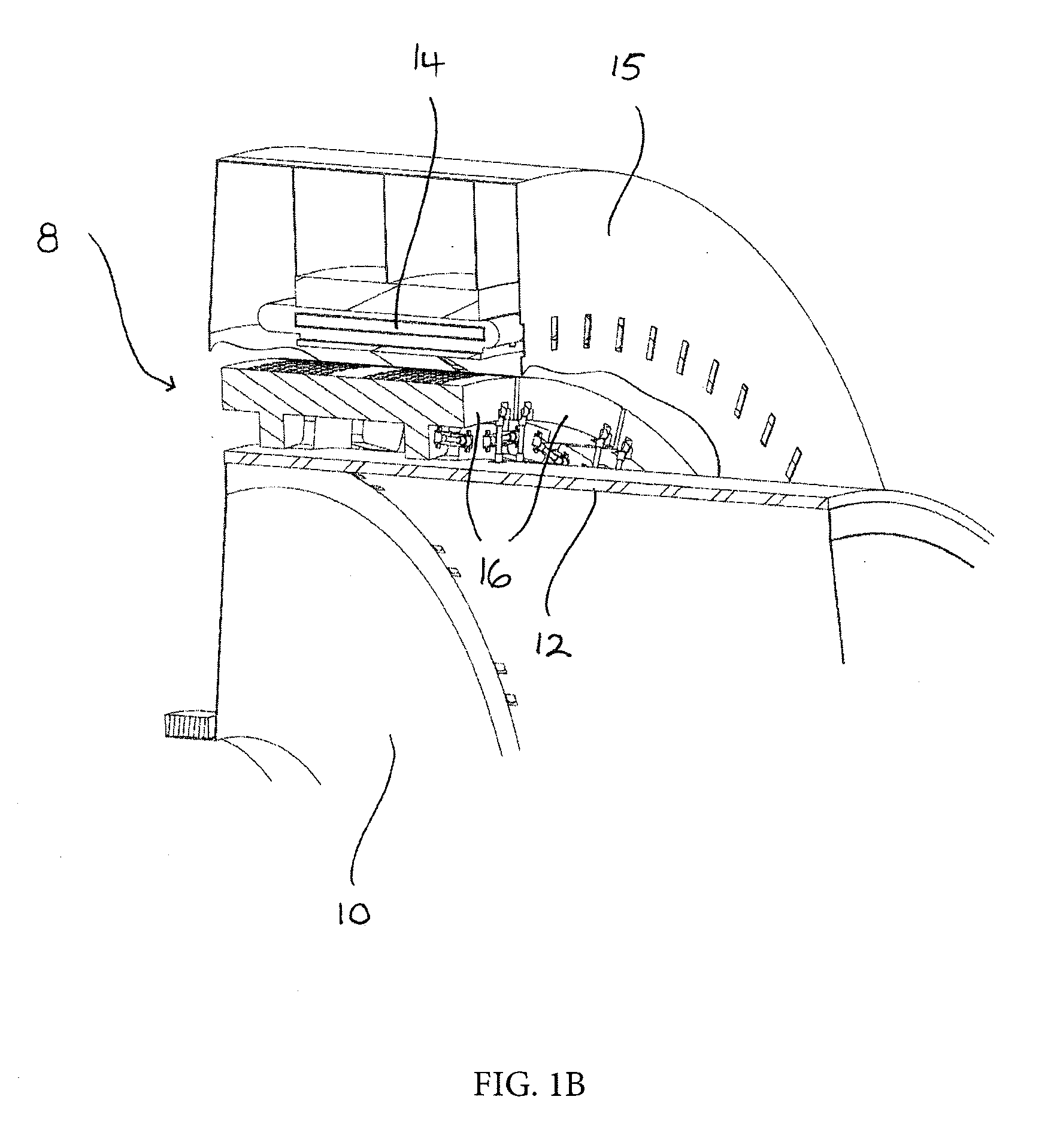
[0028]Embodiments will now be described by way of example only and with reference to the accompanying drawings.

[0029]Referring initially to FIGS. 1a and 1b, there is shown a grinding mill which employs a gearless mill drive (GMD) 8 to drive a hollow rotatable mill barrel 10 in which feed material is ground by rotation of the mill barrel 10 about an axis of rotation X-X. The mill barrel acts as the rotor 12 of the gearless mill drive 8 and is surrounded by a stator 14 typically formed by a plurality of stator segments. The stator 14 is fixed to a support frame 15.

[0030]A plurality of pole bodies 16 are independently mounted on the rotor 12 at circumferentially spaced positions around the rotor 12. A plurality of permanent magnets are affixed to an upper, and in use radially outer, surface of the pole bodies 16, for example by bonding, by way of mechanical fixings or by any other suitable means. Alternatively, the permanent magnets could be located in a housing which could be secured ...


PUM


Abstract

A gearless drive for a rotating electrical machine comprises a rotor in the form of a hollow rotatable body and having an axis of rotation and a stator surrounding the rotor. A plurality of pole bodies are independently mounted circumferentially around the rotor by a pole mounting arrangement. The stiffness of the pole mounting arrangement in the radial direction is greater than the stiffness of the pole mounting arrangement in the circumferential direction.

Description

TECHNICAL FIELD[0001]The present disclosure relates to a gearless drive for a rotating electrical machine, and more particularly to a gearless mill drive (GMD) for a grinding mill such as an autogenous (AG) mill or a semi-autogenous (SAG) mill.TECHNICAL BACKGROUND[0002]Grinding mills are widely used in mineral processing applications and the most common types are the autogenous (AG) grinding mill in which the feed material itself acts as the grinding medium and the semi-autogenous (SAG) grinding mill in which supplementary grinding material, typically steel balls, is added to the feed material.[0003]Many grinding mills employ a gearless mill drive (GMD), also commonly known as a ring motor, in which the mill barrel acts as the rotor and a stator surrounds the rotor. The mill barrel commonly includes a rigid circumferentially extending pole mounting flange and the pole bodies similarly include a rigid circumferentially extending pole support flange. The pole bodies are mounted on the...

Claims


Application Information

Patent Timeline
IPC IPC(8): H02K3/52
CPCH02K3/522B02C17/24H02K1/30H02K7/14H02K2213/09H02K2213/12B02C17/10Y02E10/72H02K3/527
Inventor BRADLEY, STUART IAN
Owner GE ENERGY POWER CONVERSION TECH
Why Eureka
Try Eureka