Method and device for controlling and/or monitoring the function of a secondary air supply in an emission control system

Inactive Publication Date: 2017-12-28
ROBERT BOSCH GMBH
View PDF3 Cites 5 Cited by
  • Summary
  • Abstract
  • Description
  • Claims
  • Application Information

AI Technical Summary

Benefits of technology

The present invention provides a method for using a cost-effective two-point lambda probe in an emission control system with multiple catalytic converters and a particulate filter. This method allows for accurate tracking control and diagnosis of the secondary air system and enables optimal operation of the particulate filter in the range of secondary air. The use of a two-point lambda probe instead of a second wide-band probe reduces the cost of the system and ensures high accuracy in the control and diagnosis of the catalytic converters and secondary air system. The method also compensates for tolerance and aging effects to ensure reliable and accurate results. Overall, this method provides a cost-effective solution for reducing particulate emissions and achieving stricter emission guidelines.

Problems solved by technology

In this system, however, the second wide-band lambda probe has functional disadvantages vis-à-vis a two-point lambda probe in this installation position.
These are on the one hand a lower accuracy of the tracking control in the range around lambda=1 and on the other hand a poorer suitability for detecting lambda breakthroughs for the diagnosis of the first catalytic converter.

Method used


Image

  • Method and device for controlling and/or monitoring the function of a secondary air supply in an emission control system
  • Method and device for controlling and/or monitoring the function of a secondary air supply in an emission control system

Examples


Embodiment Construction

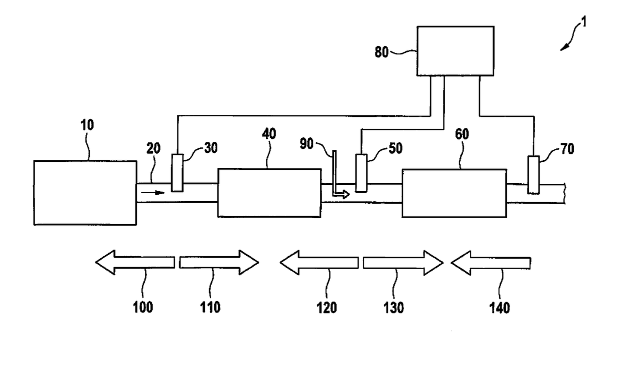
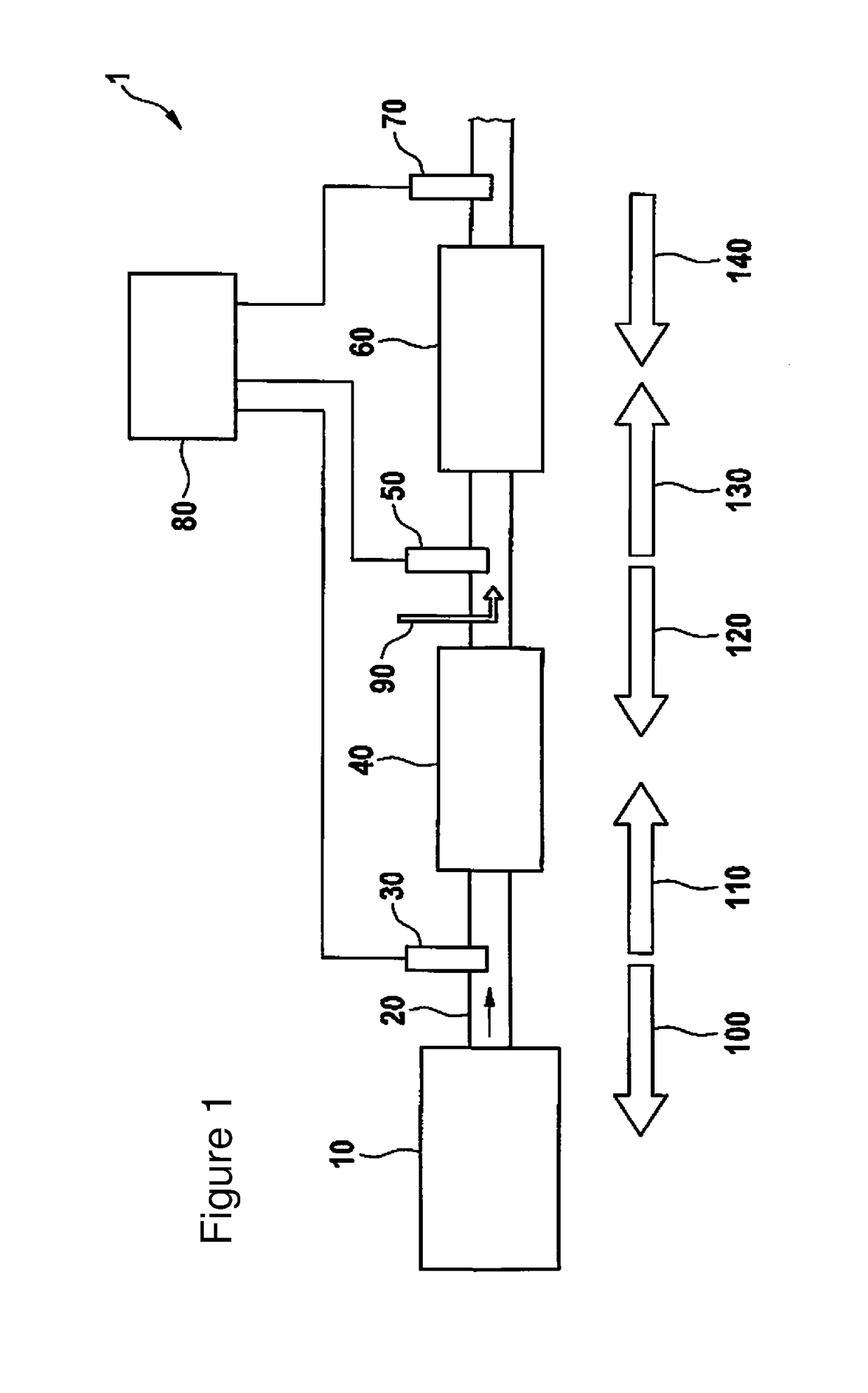
[0032]The FIGURE shows in a schematic representation an internal combustion engine 1 that includes an engine block 10, an exhaust duct 20, a lambda probe 30 that is, with respect to the direction of flow of exhaust gas, downstream of the engine block 10 and that is, in an example embodiment, implemented as a wide-band lambda probe, and a first catalytic converter 40 situated downstream of the lambda probe 30. Lambda probe 30 makes possible lambda control 100 and is used for a first balancing 110 for diagnosing the storage capacity of the first catalytic converter.

[0033]The internal combustion engine 1 further includes, downstream from first catalytic converter 40, a first two-point lambda probe 50 used for catalytic converter diagnosis-tracking control and for breakthrough detection for the diagnosis of first catalytic converter 40. The internal combustion engine 1 further includes a second catalytic converter 60 downstream of the first two-point lambda probe 50. The first two-point...


PUM


Abstract

In a method and device for controlling and / or monitoring the function of a secondary air supply in an emission control system of an internal combustion engine, the emission control system includes at least two catalytic converters situated in succession in an exhaust duct, it being possible for the second catalytic converter to be implemented as a combination of catalytic converter and particulate filter. For a secondary air diagnosis and for secondary air control, a two-point lambda probe is situated, with respect to a direction of flow of exhaust gas, downstream of the first catalytic converter. Measures are applied for compensating tolerance and aging effects of the two-point lambda probe. This results in particular in cost advantages in emission control systems for fulfilling stricter emission requirements. In particular, this makes it possible to operate the particulate filter in optimized fashion.

Description

CROSS-REFERENCE TO RELATED APPLICATIONS[0001]The present application claims priority under 35 U.S.C. §119 to DE 10 2016 211 595.2, filed in the Federal Republic of Germany on Jun. 28, 2016, the content of which is hereby incorporated by reference herein in its entirety.FIELD OF THE INVENTION[0002]The present invention relates to a method for controlling and / or monitoring the function of a secondary air supply in an emission control system of an internal combustion engine, which in its central section includes at least two catalytic converters situated in succession in an exhaust duct, it being possible for additional exhaust gas-purifying components to be situated upstream or downstream from this central section, a lambda probe being situated, with respect to the direction of flow of the exhaust gas, downstream of an engine block and upstream of the first catalytic converter, and an additional exhaust gas probe being situated upstream from an additional catalytic converter, air bein...

Claims


Application Information

Patent Timeline
IPC IPC(8): F01N3/30F01N11/00F01N13/00F01N3/021
CPCF01N3/30F01N11/007F01N3/021F01N2560/025F01N2900/08F01N2560/12F01N13/009F01N3/035F01N3/22F01N9/00F01N11/00F01N2550/14F01N2560/14F01N2900/1402F01N2900/1602F01N2900/1804Y02T10/40
Inventor MEIER, FRANKBLEI, MATTHIASFEY, MICHAELPFEIL, MICHAEL
Owner ROBERT BOSCH GMBH
Why Eureka
Try Eureka