Power amplifier circuit
a power amplifier and circuit technology, applied in the direction of duplex signal operation, transmission path division, wireless communication, etc., can solve the problems of limited maximum power supply voltage and transistor breakage, and achieve the effect of improving power-added efficiency
- Summary
- Abstract
- Description
- Claims
- Application Information
AI Technical Summary
Benefits of technology
Problems solved by technology
Method used
Image
Examples
first embodiment
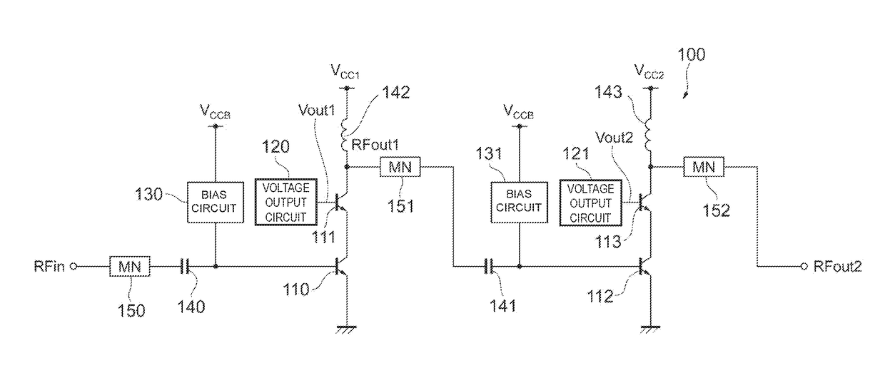
[0030]FIG. 1 illustrates an example of the configuration of a power amplifier circuit 100 according to the disclosure. In a mobile communication device, such as a cellular phone, the power amplifier circuit 100 amplifies an input radio frequency (RF) signal RFin and outputs an amplified signal RFout2. The frequency of the RF signal RFin is about several gigahertz, for example.
[0031]As shown in FIG. 1, the power amplifier circuit 100 includes bipolar transistors 110, 111, 112, and 113, voltage output circuits 120 and 121, bias circuits 130 and 131, capacitors 140 and 141, inductors 142 and 143, and matching circuits 150, 151, and 152.
[0032]The power amplifier circuit 100 includes two-stage amplifiers. The first-stage amplifier (drive stage) includes the bipolar transistors 110 and 111, while the second-stage amplifier (power stage) includes the bipolar transistors 112 and 113. Hereinafter, each pair of the bipolar transistors 110 and 111 and the bipolar transistors 112 and 113 may al...
second embodiment
[0082]FIG. 14 illustrates an example of the configuration of a power amplifier circuit 2000 according to the disclosure. The same elements as those shown in FIG. 1 are designated by like reference numerals, and an explanation thereof will be omitted. The power amplifier circuit 2000 is different from the power amplifier circuit 100 in that, as the upper-stage cascode-connected transistors, field-effect transistors (FETs) 2111 and 2113 are used instead of the bipolar transistors 111 and 113.
[0083]The FET 2111 (second transistor) is cascode-connected to the bipolar transistor 110. The FET 2113 (seventh transistor) is cascode-connected to the bipolar transistor 112. This will be discussed more specifically. A power supply voltage VCC1 is supplied to the drain of the FET 2111 via the inductor 142. The gate of the FET 2111 is connected to the voltage output circuit 120, and the source thereof is connected to the collector of the bipolar transistor 110. A signal amplified by the bipolar t...
PUM
 Abstract
Description
Claims
Application Information
 - R&D
- Intellectual Property
- Life Sciences
- Materials
- Tech Scout
- Unparalleled Data Quality
- Higher Quality Content
- 60% Fewer Hallucinations
Browse by: Latest US Patents, China's latest patents, Technical Efficacy Thesaurus, Application Domain, Technology Topic, Popular Technical Reports.
© 2025 PatSnap. All rights reserved.Legal|Privacy policy|Modern Slavery Act Transparency Statement|Sitemap|About US| Contact US: help@patsnap.com


