
Method for dynamic heat sensing in hypersonic applications

Active Publication Date: 2017-12-14
RAYTHEON CO
View PDF0 Cites 4 Cited by
  • Summary
  • Abstract
  • Description
  • Claims
  • Application Information

AI Technical Summary

Benefits of technology

The sensor system and method described in this patent have several advantages over previous sensor systems. Firstly, the system can detect surface temperatures higher than 1800 Kelvin, compared to conventional thermocouples that melt at high temperatures. Secondly, the system uses an auxiliary antenna that allows for computation of surface temperatures with a time lag of less than a second, making it faster and more accurate compared to thermocouples. Lastly, the auxiliary antenna is flexible and can perform multiple functions within the vehicle. The system is also easy to manufacture and install.

Problems solved by technology

During flight of the vehicle, exterior surfaces of the radome may be subject to high temperatures that heat components within the radome.
The temperatures around the radome may not be uniform such that certain regions of the radome may be subject to greater amounts of heat as compared with other regions.
High surface temperatures of the flight vehicle may impact performance of the hypersonic vehicle, primarily due to overly heated surfaces and possible deformation of the vehicle body in the overheated regions.
Hot gas from external flow around the vehicle may enter a gap and increase the heat flux on a respective side wall of the body, resulting in damage or even deformation to the body.
Adding components and weight to the flight vehicle may disadvantageously impact normal operation and function of the vehicle.

Method used


Image

  • Method for dynamic heat sensing in hypersonic applications
  • Method for dynamic heat sensing in hypersonic applications
  • Method for dynamic heat sensing in hypersonic applications

Examples


Embodiment Construction

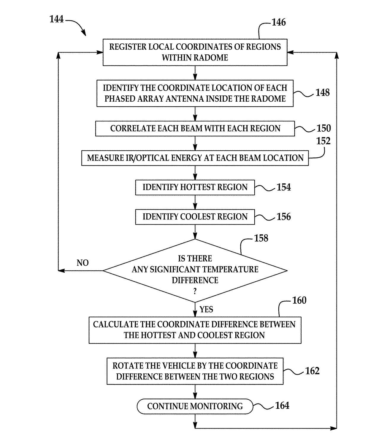
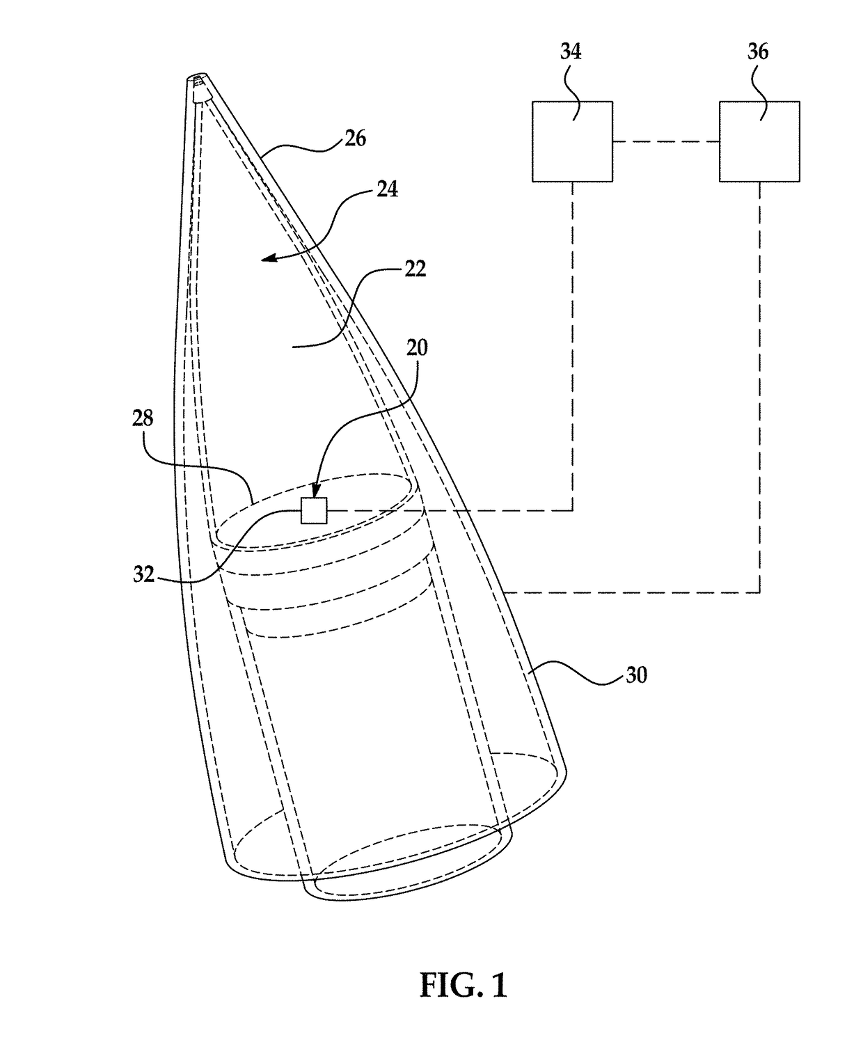
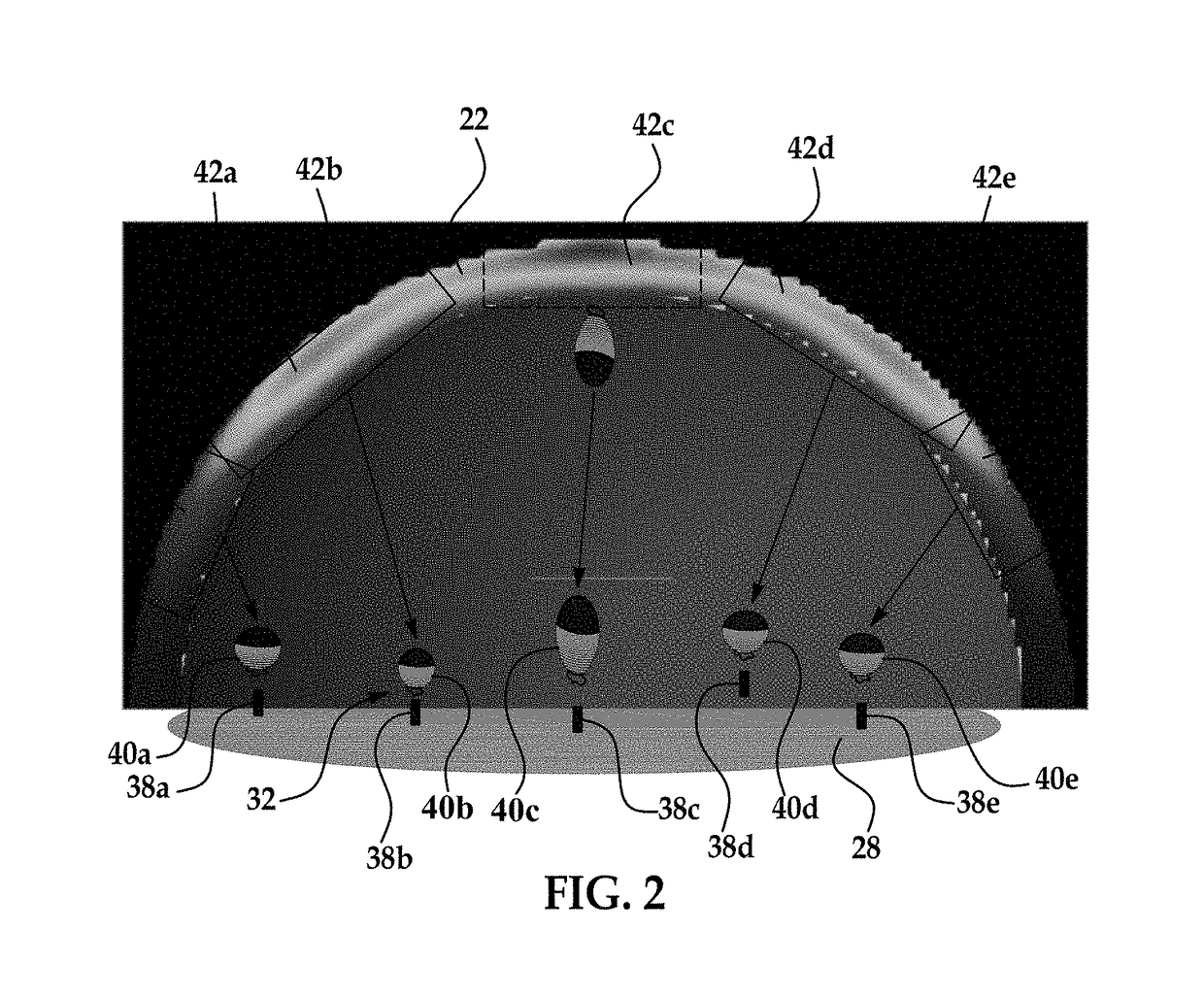
[0053]The principles described herein have particular application in flight vehicles or hypersonic vehicles such as missiles. During hypersonic flight, the surface temperatures of the body of the hypersonic vehicle increases to temperatures that affect the performance of the vehicle. The surface temperatures may range from 600 Kelvin to temperatures greater than 1800 Kelvin. Detecting the surface temperature in nearly real time is desirable for maximizing vehicle efficiency by adjusting the vehicle operation to accommodate for overly heated surface areas of the vehicle or the surrounding environment of the hypersonic vehicle. Specific surface temperatures may indicate that the vehicle is traveling through atmospheric turbulence, such that the flight path of the vehicle or orientation of the vehicle may be adjusted to equalize heat around the vehicle. A heat sensing system may be implemented in the vehicle to detect overly heated areas of the exterior surface of the vehicle.

[0054]Ref...


PUM


Abstract

A heat sensing system and method for dynamic heat sensing may be implemented in a flight vehicle having a main antenna configured for sending and / or receipt of signals. The system includes an auxiliary antenna system that is arranged within a radome of the flight vehicle for detecting temperatures around the exterior surface of the radome. The auxiliary antenna is configured for receiving and measuring infrared or optical energy. Using the measured energy, the system is configured to determine whether the detected temperature exceeds a predetermined temperature and rotating the vehicle to equalize heat around the vehicle when the current temperature exceeds the predetermined temperature.

Description

FIELD OF THE INVENTION[0001]The invention relates to a system and method for detecting surface temperatures of hypersonic vehicles.DESCRIPTION OF THE RELATED ART[0002]Conventional hypersonic flight vehicles are configured to include a radome that protects equipment used for operation of the flight vehicle, such as antennas. During flight of the vehicle, exterior surfaces of the radome may be subject to high temperatures that heat components within the radome. For example, temperatures may increase to greater than 2200 Kelvin at a nosetip region of the radome and greater than 1900 Kelvin around the main body of the radome. The temperatures around the radome may not be uniform such that certain regions of the radome may be subject to greater amounts of heat as compared with other regions. High surface temperatures of the flight vehicle may impact performance of the hypersonic vehicle, primarily due to overly heated surfaces and possible deformation of the vehicle body in the overheate...

Claims


Application Information

Patent Timeline
IPC IPC(8): H01Q1/02H01Q1/42H01Q1/28
CPCH01Q1/02H01Q1/28H01Q1/42F42B10/46F42B15/34H01Q1/002H01Q1/281H01Q5/22
Inventor STRATIS, GLAFKOS K.VANDERWYST, ANTONSUNNE, WAYNE L.DERRICK, DAVID G.
Owner RAYTHEON CO
Learn More