
End-to-end verifiable e-voting system without tallying authorities

Inactive Publication Date: 2017-12-14
UNIVERSITY OF NEWCASTLE
View PDF1 Cites 12 Cited by
  • Summary
  • Abstract
  • Description
  • Claims
  • Application Information

AI Technical Summary

Benefits of technology

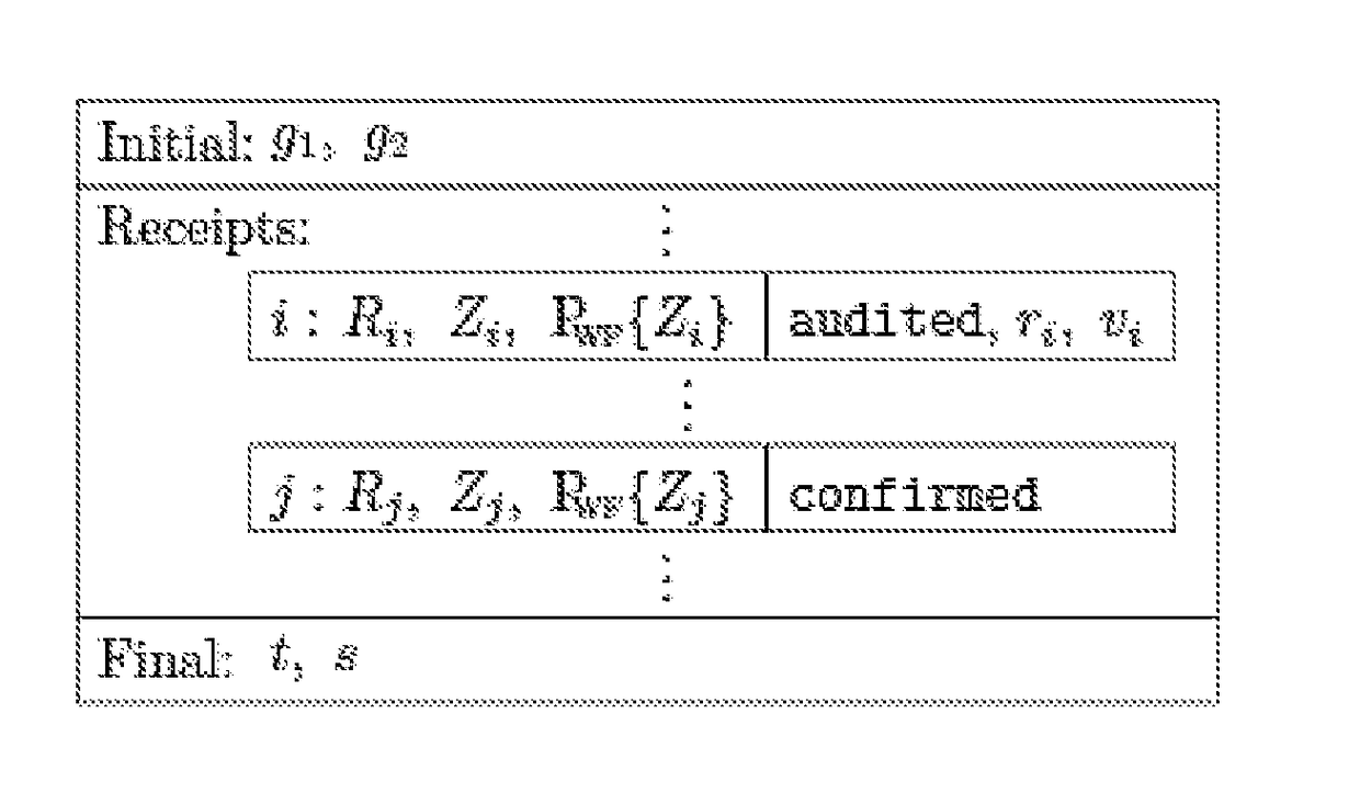
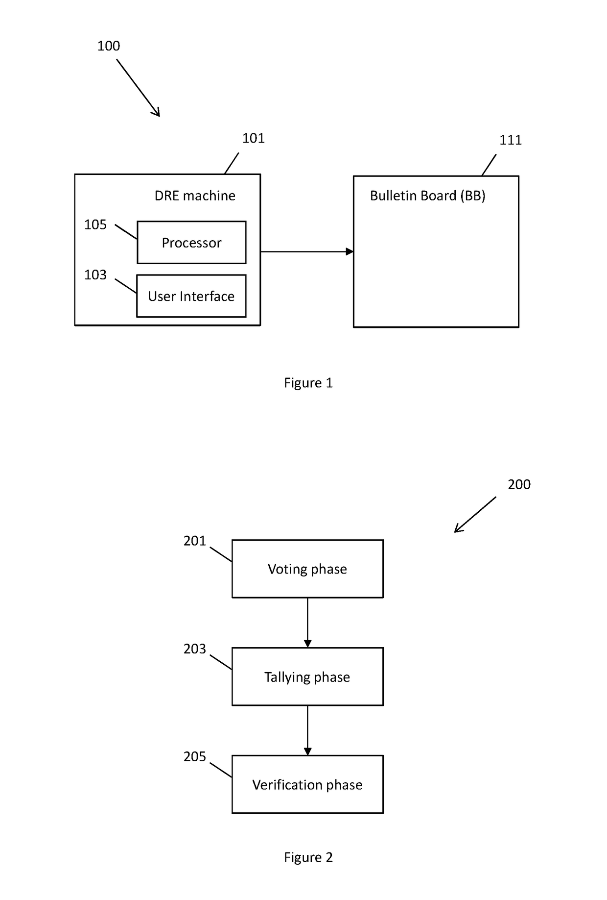
The present invention is a method for electronic voting that solves certain problems of the related art. The method involves receiving a selection of a vote from a voter, generating one or more secret values associated with the voter, calculating one or more public values based on the secret values, providing a receipt with the public values to the voter, updating a tally, and updating a sum. Overall, the invention provides a more secure and efficient method for electronic voting.

Problems solved by technology

Lack of assurance on the tallying integrity has been commonly regarded as a critical weakness of such DRE machines.
Today, nearly all of the deployed DRE systems work like a black box and offer no guarantee on integrity; consequently, their use has been abandoned in several countries such as the Netherlands, Germany and Ireland.
However, in many other countries, these (unverifiable) DRE machines continue to be extensively used.
The introduction of an external set of TAs however introduces difficulties in the implementation.
Furthermore, the quorum should be set sufficiently large such that collusion among TAs is infeasible, but at the same time, sufficiently small such that the process is error-tolerant (e.g., in the case n out of n TAs need to be present, the loss of a single key share will render the election result non-computable).
Reconciling the two is not an easy task.
), the implementation of TAs has proved to be one particularly difficult issue.
One problem with DRE-i is that its pre-computation strategy inevitably introduces the requirement of keeping the pre-computed data secret.
Leakage of those data may endanger the voter's privacy.
However, the use of tamper-resistant hardware may significantly drive up the cost for each DRE machine.
Furthermore, designing secure API for tamper-resistant hardware is a challenging problem in its own.
Finally, in the case that the tamper resistance is compromised, the privacy of all votes will be lost.

Method used


Image

  • End-to-end verifiable e-voting system without tallying authorities
  • End-to-end verifiable e-voting system without tallying authorities
  • End-to-end verifiable e-voting system without tallying authorities

Examples


Embodiment Construction

[0027]The following description of exemplary embodiments of the present invention, with reference to the accompanying drawings, is provided to assist in a comprehensive understanding of the present invention, as defined by the claims. The description includes various specific details to assist in that understanding but these are to be regarded as merely exemplary. Accordingly, those of ordinary skill in the art will recognize that various changes and modifications of the embodiments described herein can be made without departing from the scope of the present invention, as defined by the claims.

[0028]The terms and words used in this specification are not limited to the bibliographical meanings, but, are merely used to enable a clear and consistent understanding of the present invention.

[0029]The same or similar components may be designated by the same or similar reference numerals, although they may be illustrated in different drawings.

[0030]Detailed descriptions of elements, feature...


PUM


Abstract

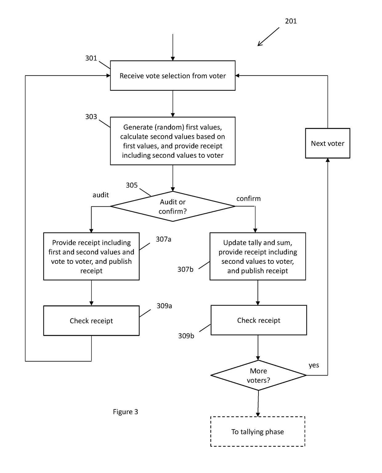
A method for electronic voting is provided. The method comprises receiving a selection of a vote vi from a voter, generating one or more first values associated with the voter, calculating one or more second values based on the one or more first values, providing a first type of receipt including the one or more second values to the voter, updating a tally, t, based on the vote vi, updating a sum, s, based on the one or more first values, and publishing the receipt including the one or more second values.

Description

FIELD OF THE INVENTION[0001]The present invention relates to an end-to-end verifiable e-voting system. In particular, certain embodiments of the present invention provide an end-to-end verifiable e-voting system that does not require a trusted tallying authority.BACKGROUND OF THE INVENTION[0002]Direct-recording electronic (DRE) machines have been extensively used for in-person voting at polling stations around the world. In a typical process, a legitimate voter obtains a random token after being authenticated at the polling station. The voter then enters a private booth and presents the token to a DRE machine. The token is for one-time use and allows the voter to cast only one vote. Usually, the DRE machine has a touch screen to record the electronic vote directly from the voter (hence the name direct-recording electronic). The machine may tally the vote in real time, or store the votes in a memory card and tally later. In either case, the machine works like a black box: if an attac...

Claims


Application Information

Patent Timeline
IPC IPC(8): G07C13/02H04L9/08H04L9/30
CPCG07C13/02H04L9/30H04L9/08H04L9/3013H04L9/3218H04L2209/463G06Q2230/00G07C13/00
Inventor HAO, FENGSHAHANDASHTI, SIAMAK F.
Owner UNIVERSITY OF NEWCASTLE
Learn More