Eureka AIR delivers breakthrough ideas for toughest innovation challenges, trusted by R&D personnel around the world.

Conduit body with super fitting

Active Publication Date: 2017-12-14
ATKORE STEEL COMPONENTS INC
View PDF1 Cites 5 Cited by
  • Summary
  • Abstract
  • Description
  • Claims
  • Application Information

AI Technical Summary

Benefits of technology

The versatile connector assembly described in this patent has several technical benefits. First, it is designed to resist contamination from dust and moisture. Second, it can accommodate both threaded and unthreaded conduits in different situations. Third, it reduces the potential for damage to conductors.

Problems solved by technology

The components brought together by connector assemblies can be sensitive to contaminants such as dust and moisture.
If a proper seal is not formed between and among the elements of the connector assembly, the electrical and mechanical components may be susceptible to contamination and resulting in damage.
Furthermore, traditional connector assemblies are not able to accommodate both threaded and unthreaded conduits.
Still furthermore, traditional connector assembly bodies can have rough internal openings that may cut or damage conductors, especially when being pulled.

Method used


Image

  • Conduit body with super fitting
  • Conduit body with super fitting
  • Conduit body with super fitting

Examples


Embodiment Construction

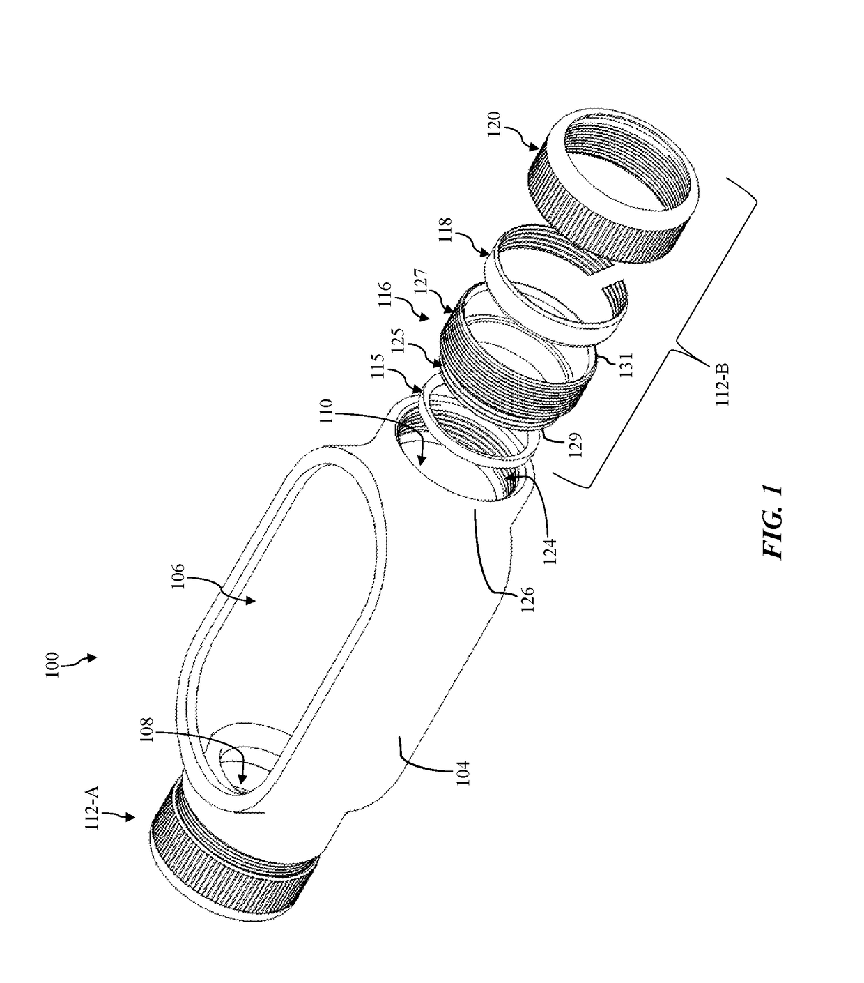
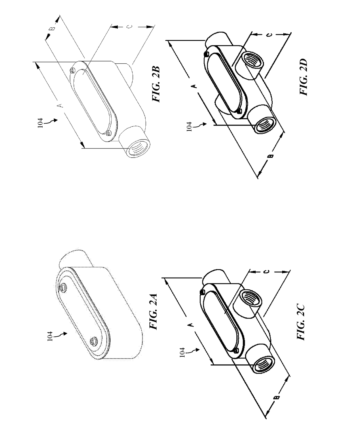
[0018]Assemblies and in accordance with the present disclosure will now be described more fully hereinafter with reference to the accompanying drawings, where embodiments of the system and method are shown. The assemblies may be embodied in many different forms and are not be construed as being limited to the embodiments set forth herein. Instead, these embodiments are provided so this disclosure will be thorough and complete, and will fully convey the scope of the system and method to those skilled in the art.

[0019]For the sake of convenience and clarity, terms such as “top,”“bottom,”“upper,”“lower,”“vertical,”“horizontal,”“lateral,” and “longitudinal” will be used herein to describe the relative placement and orientation of these components and their constituent parts. The terminology will include the words specifically mentioned, derivatives thereof, and words of similar import.

[0020]As used herein, an element or operation recited in the singular and proceeded with the word “a” o...


PUM


Abstract

Provided herein are approaches for forming a connection with a conduit body. In one approach, an exemplary connector assembly a conduit body having a conduit inner surface opposing a conduit outer surface, at least a portion of the conduit inner surface being a threaded portion. The connector assembly may further include a compression ring extending from a first circumferential end to a second circumferential end, wherein the first circumferential end is complementarily engageable with the second circumferential end, wherein the compression ring includes a first axial end and a second axial end, and wherein the compression ring has a circumferential gap between the first circumferential end and the second circumferential end in an uncompressed configuration. The connector assembly may further include a bushing positioned within the threaded portion of the conduit inner surface of the conduit body.

Description

FIELD OF THE DISCLOSURE[0001]The disclosure relates generally to conduit connector assemblies and, more particularly, to conduit connector assemblies including a compression ring and bushing.BACKGROUND OF THE DISCLOSURE[0002]Electrical and mechanical components such as cables often need to be connected with each other through various angles and configurations. Conduits (e.g., pipes) and junction boxes may be used to house electrical cables, and connectors are used to join conduits with each other and / or with other components such as junction boxes in desired configurations. Connector assemblies make use of such connector elements as connector bodies, nuts, gaskets, etc., to provide the configurations desired for the conduits that house electrical and mechanical components.[0003]The components brought together by connector assemblies can be sensitive to contaminants such as dust and moisture. If a proper seal is not formed between and among the elements of the connector assembly, the...

Claims


Application Information

Patent Timeline
IPC IPC(8): F16L19/06F16L19/07
CPCF16L19/07F16L19/061H02G3/0462H02G3/0616F16L19/065H02G3/04H02G3/06
Inventor SHEMTOV, SAMI
Owner ATKORE STEEL COMPONENTS INC
Why Eureka
Eureka Blog
Learn More