
Shaft-hub connection

a technology of shaft and hub, which is applied in the direction of mechanical equipment, functional valve types, couplings, etc., can solve the problems of affecting the reliability of the shaft-hub connection during operation, and the difficulty of fitting the shaft together with the hub,

Active Publication Date: 2017-12-07
MAGNA POWERTRAIN AG & CO KG
View PDF2 Cites 0 Cited by
  • Summary
  • Abstract
  • Description
  • Claims
  • Application Information

AI Technical Summary

Benefits of technology

The invention is a new type of shaft-hub connection that has two main benefits: its design is simple and it works well. The connection has a gas-permeable closure element at the end of the hub, which helps to equalize pressure between the hub and the external region and makes it easy to connect the shaft and hub together. This closure element also prevents solid and liquid materials from entering the hub and helps to keep lubricants in the connection. Additionally, a filter element can be included in the connection to improve its performance.

Problems solved by technology

However, during the fitting together of shaft and hub, the problem arises that, when a hub is closed on one side, a positive pressure arises in a cavity between that part of the shaft which extends in the hub and the closed hub end, the positive pressure making the fitting of the shaft together with the hub more difficult and having a negative influence on the reliability of the shaft-hub connection during operation, i.e. during a transmission of torque via the shaft-hub connection.

Method used


Image

  • Shaft-hub connection
  • Shaft-hub connection
  • Shaft-hub connection

Examples


Embodiment Construction

[0029]Example embodiments are provided so that this disclosure will be thorough, and will fully convey the scope to those who are skilled in the art. Numerous specific details are set forth such as examples of specific components, devices, and methods, to provide a thorough understanding of embodiments of the present disclosure. It will be apparent to those skilled in the art that specific details need not be employed, that example embodiments may be embodied in many different forms and that neither should be construed to limit the scope of the disclosure. In some example embodiments, well-known processes, well-known device structures, and well-known technologies are not described in detail.

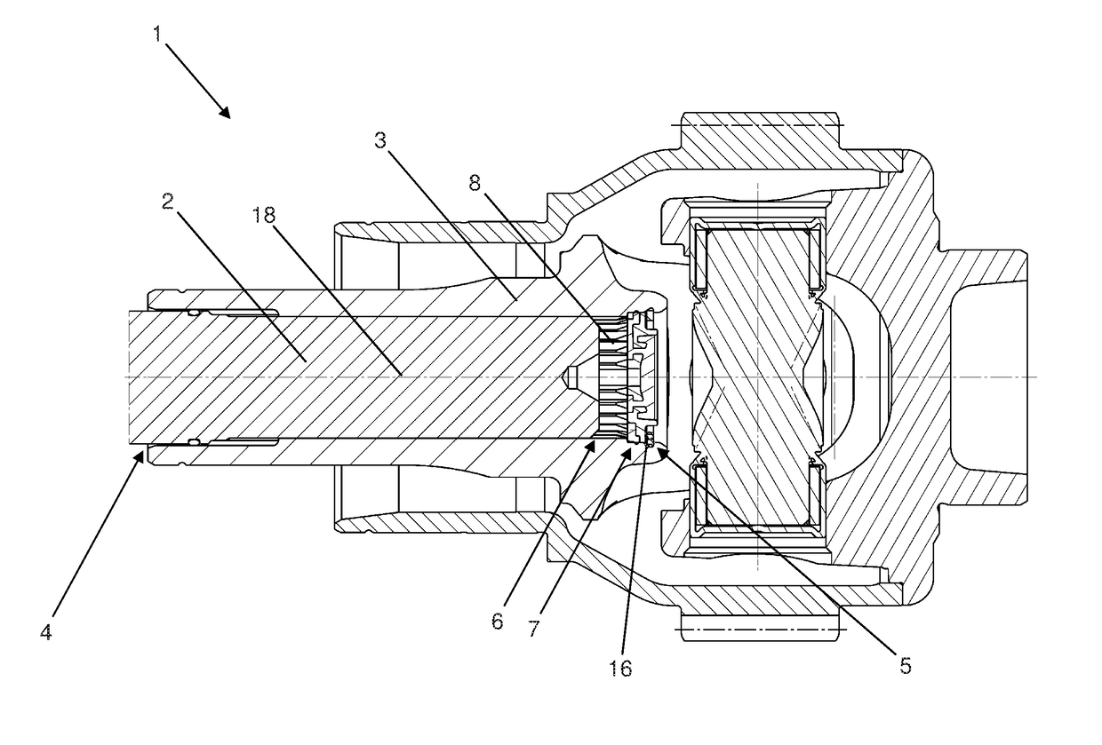
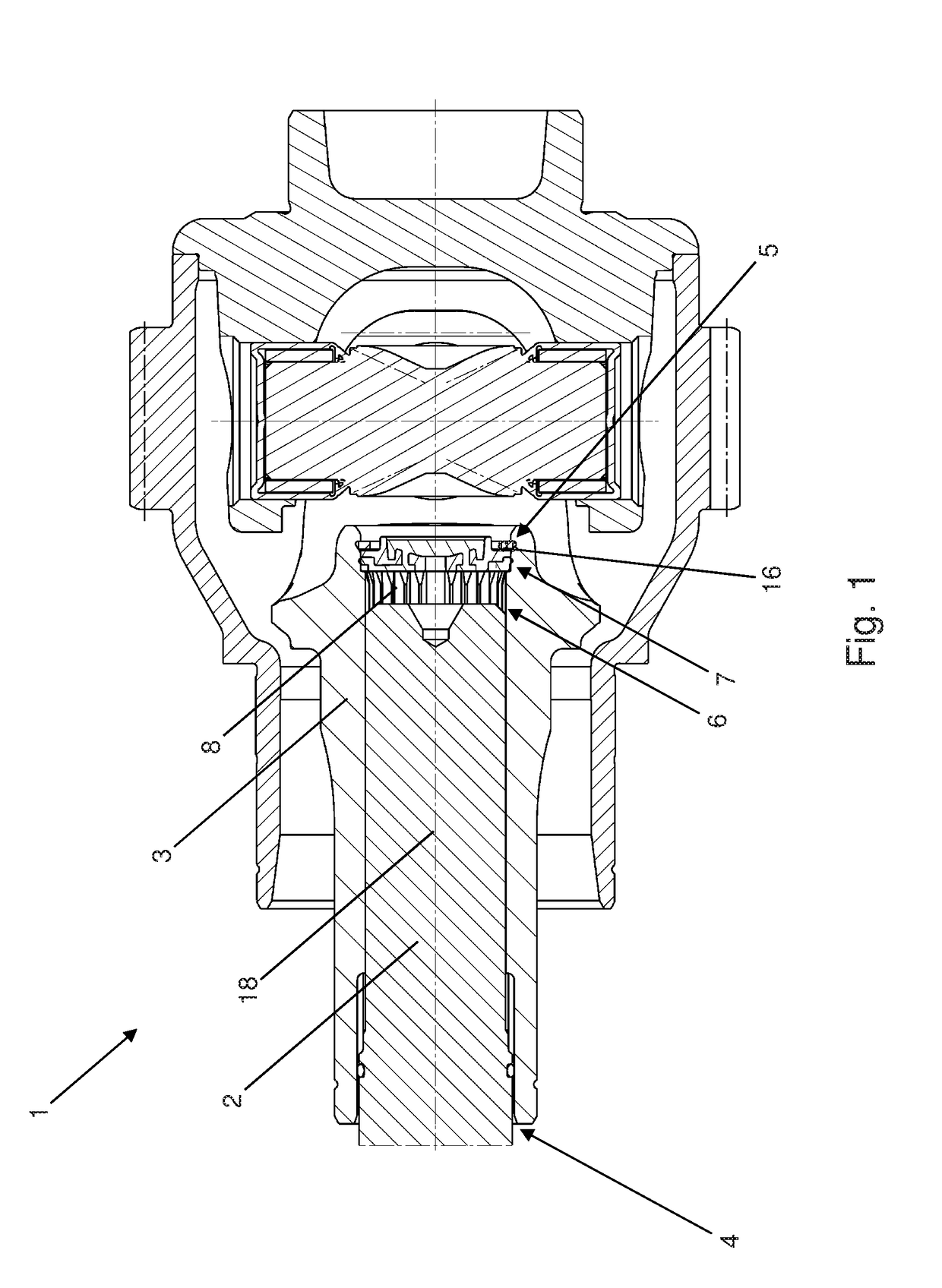
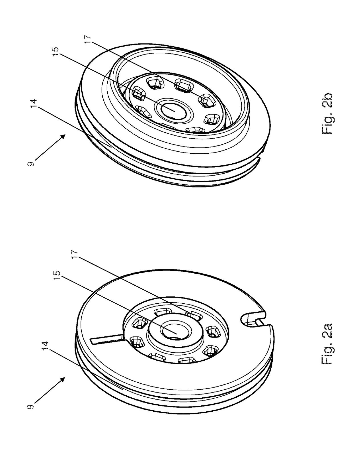
[0030]FIG. 1 shows a sectional view of an exemplary shaft-hub connection 1 as part of a gearbox of a motor vehicle. The shaft-hub connection 1 in FIG. 1 comprises a shaft 2 with an external toothing and a hub 3 which is of substantially tubular design and has an internal toothing corresponding to...


PUM


Abstract

A shaft-hub connection, in particular for a gearbox of a motor vehicle, comprising a shaft, at least one hub which is connected to the shaft, wherein the hub is of tubular design and a shaft end of the shaft engages on a first hub end of the hub, and a closure element is arranged on a second hub end of the hub. A cavity is formed between the closure element and the shaft end of the shaft. The closure element is designed in such a manner that gaseous medium can escape via the closure element in the event of a positive pressure in the cavity.

Description

CROSS-REFERENCE TO RELATED APPLICATIONS[0001]This application claims the benefit and priority of German Application No. DE102016209819.5 filed Jun. 3, 2016. The entire disclosure of the above application is incorporated herein by reference.TECHNICAL FIELD[0002]The present invention relates generally to a shaft-hub connection for use in a gearbox of a motor vehicle. More particularly, the shaft-hub connection comprises a shaft, at least one hub which is connected to the shaft, wherein the hub is of tubular design and a shaft end of the shaft engages on a first hub end of the hub, and a closure element is arranged on a second hub end of the hub.BACKGROUND OF THE INVENTION[0003]This section provides background information related to the present disclosure which is not necessarily prior art.[0004]Shaft-hub connections are widespread in the field of mechanical engineering. They serve for transmitting a torque from a shaft to a hub, or vice versa.[0005]A shaft-hub connection has to be pro...

Claims


Application Information

Patent Timeline
IPC IPC(8): F16H57/04F16K17/02
CPCF16K17/02F16H57/04F16D3/84F16D1/10F16D3/06F16D3/387F16D3/41F16D2001/103F16D2300/06
Inventor LAFER, ALOISSCHLACHTER, PHILIPP
Owner MAGNA POWERTRAIN AG & CO KG
Learn More