
Disc-shaped heater and heater-cooling-plate assembly

a heater and cooling plate technology, applied in the direction of ohmic-resistance heating, ohmic-resistance heating details, electrical devices, etc., can solve the problems of difficult to equalize difficulty in sufficiently equalizing the temperature over the wafer, so as to achieve easy equalization and reduce the number of temperature singular points

Active Publication Date: 2017-11-30
NGK INSULATORS LTD
View PDF9 Cites 6 Cited by
  • Summary
  • Abstract
  • Description
  • Claims
  • Application Information

AI Technical Summary

Benefits of technology

The present invention is a ceramic or resin base disc-shaped heater that is used for temperature control during semiconductor device manufacturing. The heater has a large number of heating elements and can be connected to a cooling plate through mounting connectors or flexible printed circuit boards. The design also reduces the number of temperature singular points, making it easier to control the temperature over the entire heater surface. In addition, the base of the heater can be a resin base, which facilitates the use of an electrostatic chuck or sheet heater for temperature equalization control. The heater-cooling-plate assembly also includes a reduced number of terminal collection regions, further reducing temperature singular points.

Problems solved by technology

Unfortunately, the ceramic heater according to PTL 1 has a problem that it is difficult to sufficiently equalize the temperature over a wafer placed on the heating surface of the ceramic base.
When the number of temperature singular points is large, it is difficult to equalize the temperature over the wafer.

Method used


Image

  • Disc-shaped heater and heater-cooling-plate assembly
  • Disc-shaped heater and heater-cooling-plate assembly
  • Disc-shaped heater and heater-cooling-plate assembly

Examples


Embodiment Construction

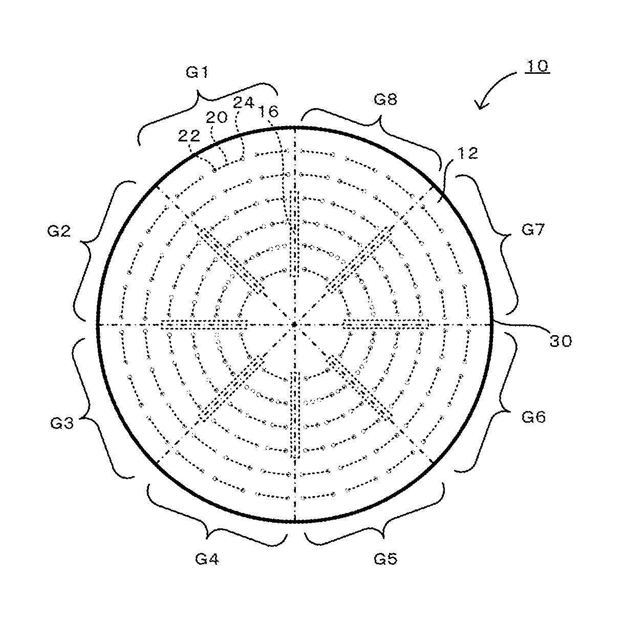
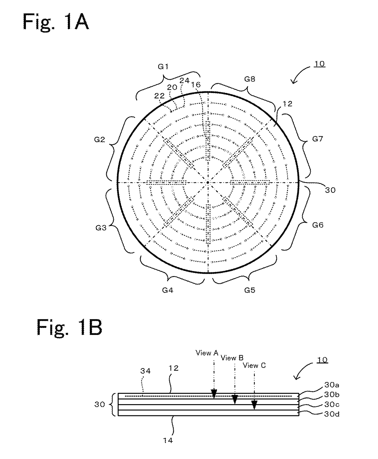
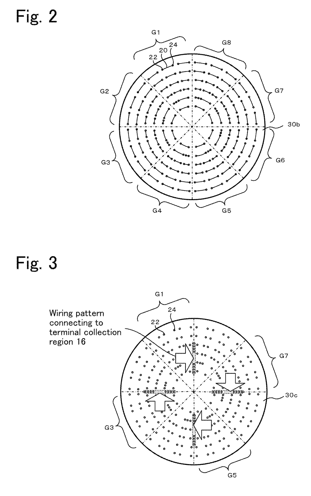
[0029]FIGS. 1A and 1B illustrate an electrostatic chuck heater 10 according to the present embodiment. FIG. 1A is a plan view, and FIG. 1B is a front view. FIG. 2 is a view indicated by arrow A, FIG. 3 is a view indicated by arrow B, and FIG. 4 is a view indicated by arrow C. FIG. 5 is a bottom view of the electrostatic chuck heater 10.

[0030]As illustrated in FIG. 1, the electrostatic chuck heater 10 includes a disc-shaped ceramic base 30 and a plurality of heating elements 20 embedded in the ceramic base 30. The ceramic base 30 is obtained by stacking and joining a plurality of discs made of a ceramic, such as alumina or aluminum nitride. In this example, first to fourth layers 30a to 30d are stacked and joined together. A top surface 12 of the electrostatic chuck heater 10, which serves as a wafer mounting surface, is divided into multiple zones. The heating elements 20, which each include a positive electrode terminal 22 and a negative electrode terminal 24, are embedded in the c...


PUM


Abstract

An electrostatic chuck heater 10 includes a disc-shaped ceramic base 30 and a plurality of heating elements 20 embedded in the ceramic base 30. A top surface 12 of the electrostatic chuck heater 10, which serves as a wafer Mounting surface, is divided into multiple zones. The heating elements 20, which each include terminals 22 and 24, are embedded in the ceramic base 30 in the respective zones. Terminal collection regions 16 are provided on a bottom surface 14 of the electrostatic chuck heater 10. The number of terminal collection regions 16 (eight in this example) is smaller than the total number of heating elements 20. The terminals 22 and 24 of each of the heating elements 20 are connected to one of the terminal collection regions 16 through the ceramic base 30.

Description

[0001]The present application claims priority from U.S. Provisional Application No. 62 / 271,581, filed on Dec. 28, 2015, the entire contents of which are incorporated herein by reference.BACKGROUND OF THE INVENTION1. Field of the Invention[0002]The present invention relates to a disc-shaped heater and a heater-cooling-plate assembly.2. Description of the Related Art[0003]Disc-shaped ceramic heaters have been known. For example, PTL 1 discloses a ceramic heater in which a heating surface is divided into a plurality of zones and resistance heating elements are embedded in a ceramic base in the respective zones. In this ceramic heater, each resistance heating element has independent input / output terminals. The bottom surface of the ceramic base has holes at positions such that the holes oppose the respective input / output terminals. Each input / output terminal is connected to a lead wire through the corresponding hole by, for example, brazing.CITATION LISTPatent Literature[0004]PTL 1: JP ...

Claims


Application Information

Patent Timeline
Patent Type & Authority Applications(United States)
IPC IPC(8): H01L21/3065H01L21/683H01L21/67H05B3/08H05B3/28
CPCH01L21/3065H01L21/6831H05B3/08H01L21/67248H05B3/283H01L21/67103H01L21/02H01L21/67109
Inventor TAKEBAYASHI, HIROSHITORII, KENGO
Owner NGK INSULATORS LTD
Learn More