
Pipe connecting device using rotary wedge

a technology of connecting device and pipe, which is applied in the direction of couplings, mechanical equipment, etc., can solve the problems of difficult to uniformly apply a force to the entire wedge, high manufacturing cost, and low economic efficiency, and achieve the effect of convenient separation

Inactive Publication Date: 2017-11-30
KIM SUKYOON
View PDF0 Cites 5 Cited by
  • Summary
  • Abstract
  • Description
  • Claims
  • Application Information

AI Technical Summary

Benefits of technology

The present invention provides a rotary wedge pipe connecting device that has a simple structure, small parts, and is economic. It can be connected by one-touch operation regardless of pipe material and is applicable to various kinds of pipes, including seamless pipe, welded pipe, thin pipe, and PE pipe. It is easy to recycle resource because pipes can be easily separated. The rotary wedge has overlapping teeth that can adjust to the tolerance of large-caliber pipes. The cross-sectional shape of the rotary corner ensures stable rotation of the rotary wedge. The elastic member applies three forces from the circumferential surface to the center of the circle, maintaining its function even if the size of the connecting device is increased or the material is changed.

Problems solved by technology

The above-mentioned conventional one-touch pipe connection device is limited by being applied only to the connection of a small-caliber lightweight stainless steel pipe.
Since the spring pushes the sliding wedge in the pipe length direction, it is difficult to uniformly apply a force to the entire wedge as the larger diameter increases.
It is difficult to apply to a pipe connection having a large-caliber, and the connection device for a thick pipe is difficult to manufacture, and there is a disadvantage that the manufacturing cost is high and the economic efficiency is low.
Further, when a high pressure is applied to the fluid, it is difficult to remove the sliding wedge by sliding the sliding wedge into a narrow space between the pipe and the inclined surface, which makes it difficult to remove the pipe.
Further, it can accomplish connection work by one-touch operation regardless pipe material, and thus can shorten the working period.

Method used


Image

  • Pipe connecting device using rotary wedge
  • Pipe connecting device using rotary wedge
  • Pipe connecting device using rotary wedge

Examples


first embodiment

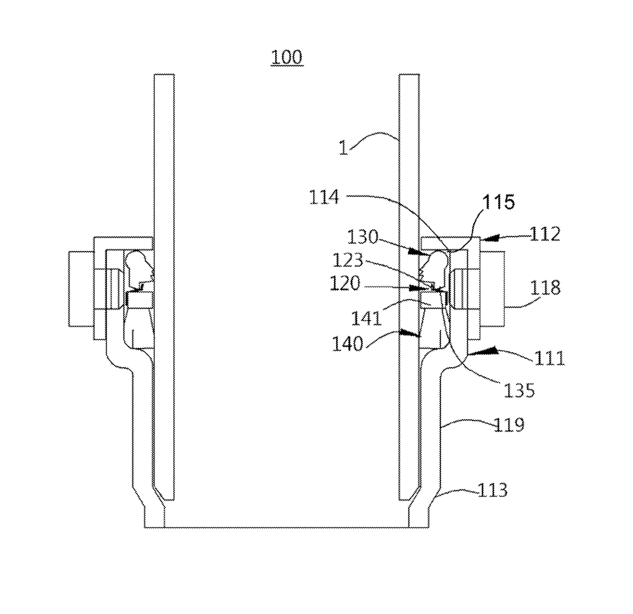
[0060]Hereinafter, the shape and function of the connecting body, the rotary wedge, the wedge groove, the elastic member, and the sealing member are described. For convenience, reference denotations are added for the first embodiment, and reference numerals used only for particular embodiments will be given to the particular embodiments.

[0061]The connecting body 110 of the present invention includes a first tube 111 that is open toward an incoming pipe and has a stop jaw 113 at an end thereof to limit the amount of insertion of the pipe, a second tube 112 that is coupled to the first tube and forms an inlet, a wedge groove 115 that is a space in which a rotary wedge 130 is installed, and a rotary corner 114 provided in the wedge grove 115 and having a L-shaped cross section for allowing the rotary wedge to rotate smoothly in place. Here, the tube refers to it having a cylindrical shape.

[0062]The first tube 111 and the second tube 112 are screwed together to complete the connecting b...

second embodiment

[0074]An elastic member 220 made of rubber, which is a polymer compound, can be conveniently fabricated in one body along with a sealing member 240. The rubber material elastic member 220 of the present invention is manufactured in one body along with the sealing member to provide a rotating force to the rotary wedge, and the isolation walls 217 are provided between rotary wedges 230 to prevent the rotary wedge from escaping off and to prevent infiltration of rainwater and sewage. Thus, it is useful for non-pressure or low-pressure connections. In the second embodiment, the rubber material elastic member 220 is applied, and the elastic member 220 is illustrated in FIG. 5. It is useful that when the rotary wedge has no false tooth, a wedge groove 215 having a trapezoidal shape when viewed from the center of the circle can be used to prevent the detachment of the rotary wedge and increase the area of the teeth of the rotary wedge.

third embodiment

[0075]In the third embodiment, a torsion spring is shown as an elastic member. The torsion springs 320 provided on both sides of the rotary wedge smoothly rotate the rotary wedge 330, so that they are suitable for a high-pressure hydraulic test jig or a large pipe connecting apparatus. In this case, it is preferable that a rotary protrusion 336 is provided so that the rotary wedge 330 does not escape off and that the rotary protrusion 336 is inserted into the coil of the torsion spring. That is, the rotary wedge fastening device and the torsion spring can be suitably used to exhibit the optimum function. A resilient part 322 for transmitting a rotational force is located between the circumferential surface of a wedge groove 315 and the rotary wedge. The torsion spring 320 is preferably installed in a space provided in the wedge groove 315 and fastened to the first tube 311 using a coupler 325. Although the coupler 325 can be used in various ways, the present invention suggests the u...


PUM


Abstract

A pipe connecting device comprises a connecting body including a first tube having a stop jaw at an end thereof and a second tube coupled to the first tube by a fastener and having an opening for insertion of a pipe, wherein a wedge groove is formed in the connecting body and includes rotary corners having a L-shaped cross section and surrounding a circumference of the pipe, rotary wedges each including a rotary part and an extension part, wherein the rotary part is provided in the wedge groove, has a semicircular cross section, and rotates while in tight contact with the rotary corners, and wherein the extension part is formed integrally with the rotary part, has teeth, and contacts the pipe, an elastic member contacting the rotary wedges to transfer a rotational force to the rotary wedges, and a sealing member embedded in the connecting body.

Description

CROSS-REFERENCE TO RELATED APPLICATIONS[0001]This patent application is a national-stage application of International Patent Application No. PCT / KR2015 / 014245, filed on Dec. 24, 2015, which claims priority under 35 U.S.C. §119 to Korean Patent Application No. 10-2015-000009, filed on Jan. 1, 2015, and Korean Patent Application No.: 10-2015-0183732, filed on Dec. 22, 2105 in the Korean Intellectual Property Office, the disclosures of which are incorporated by reference herein in their entireties.TECHNICAL FIELD[0002]The present invention relates to a pipe fastening and connecting device, and more specifically, to a pipe connecting device using a rotary wedge, in which large-caliber pipes as well as small-caliber pipes are easily and firmly connected in a one-touch manner, which is applied to steel pipes and PE pipes regardless of the pipe materials, in which the unit cost can be decreased by reducing the number of parts, which can be used as joints for piping with sealing functionali...

Claims


Application Information

Patent Timeline
Patent Type & Authority Applications(United States)
IPC IPC(8): F16L37/092
CPCF16L37/0925F16L21/03F16L17/035F16L21/08F16L25/065F16L37/0844F16L37/0845F16L37/0927
Inventor KIM, SUKYOON
Owner KIM SUKYOON
Learn More