Ion implanter comprising integrated ventilation system

Active Publication Date: 2017-11-23
ENTEGRIS INC
View PDF1 Cites 0 Cited by
  • Summary
  • Abstract
  • Description
  • Claims
  • Application Information

AI Technical Summary

Benefits of technology

The present disclosure relates to an ion implantation system and method that includes an ion implanter and a gas box for holding gas supply vessels. The system has two ventilation assemblies: one for exhausting gas from the housing and another for exhausting gas from the gas box. A monitoring and control assembly is also included for monitoring and responding to gas hazard events, which can prevent gas-dispensing operation and adjust the flow rate of the gas box exhaust gas to the treatment apparatus. The technical effects of this system and method include improved safety and efficiency in ion implantation processes.

Problems solved by technology

To meet these strict specifications, the air is subjected to filtration, cooling, humidification / dehumidification, and purification operations, which entail substantial expense in respect of the associated capital equipment and operating costs.
The ventilation gas makeup, conditioning, and exhaust operations associated with the ion implantation apparatus therefore represent a critical aspect of the safe and efficient performance of such apparatus, but as mentioned above involve substantial capital equipment and operating costs in the manufacturing facilities in which they are employed.

Method used


Image

  • Ion implanter comprising integrated ventilation system
  • Ion implanter comprising integrated ventilation system

Examples


Embodiment Construction

[0014]The present disclosure relates to ion implantation apparatus and methods.

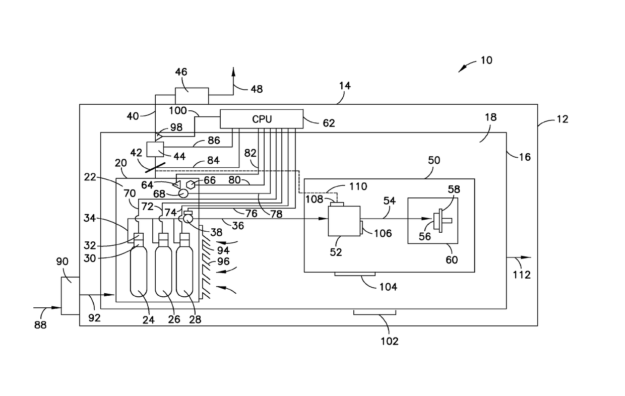
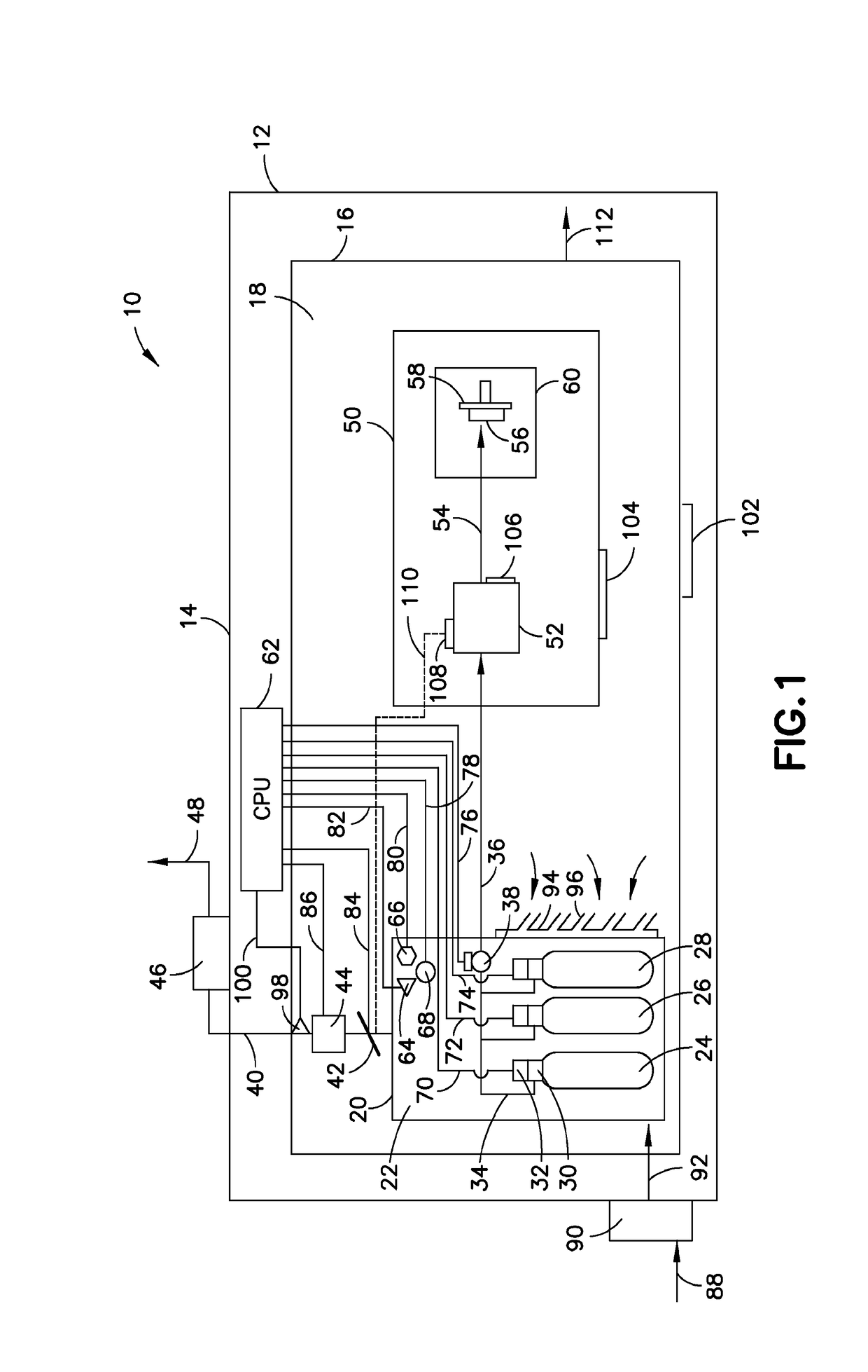
[0015]The ion implantation system configuration of the present disclosure enables elimination of flow circuitry that otherwise is employed for flowing shell exhaust from an implanter to vent same to the atmosphere, e.g., from a rooftop vent of the semiconductor manufacturing facility, as has heretofore been the conventional practice in semiconductor manufacturing fabs.

[0016]The shell exhaust is the ventilation gas that is flowed through and subsequently discharged from the housing of the ion implantation system. The gas box is disposed within the housing of the ion implantation system, and is in restricted gas communication with the gas in the housing that is outside the gas box. For example, the gas box may be provided with an access door or other access structure that enables passage of gas into the gas box from the exterior environment of the gas box within the housing, e.g., through louvers in the acc...


PUM

PropertyMeasurementUnit
Pressureaaaaaaaaaa
Flow rateaaaaaaaaaa
Frequencyaaaaaaaaaa

Abstract

An ion implantation system is described, including: an ion implanter comprising a housing defining an enclosed volume in which is positioned a gas box configured to hold one or more gas supply vessels, the gas box being in restricted gas flow communication with gas in the enclosed volume that is outside the gas box; a first ventilation assembly configured to flow ventilation gas through the housing and to exhaust the ventilation gas from the housing to an ambient environment of the ion implanter; a second ventilation assembly configured to exhaust gas from the gas box to a treatment apparatus that is adapted to at least partially remove contaminants from the gas box exhaust gas, or that is adapted to dilute the gas box exhaust gas, to produce a treated effluent gas, the second ventilation assembly comprising a variable flow control device for modulating flow rate of the gas box exhaust gas between a relatively lower gas box exhaust gas flow rate and a relatively higher gas box exhaust gas flow rate, and a motive fluid driver adapted to flow the gas box exhaust gas through the variable flow control device to the treatment apparatus; and a monitoring and control assembly configured to monitor operation of the ion implanter for occurrence of a gas hazard event, and thereupon to responsively prevent gas-dispensing operation of the one or more gas supply vessels, and to modulate the variable flow control device to the relatively higher gas box exhaust gas flow rate so that the motive fluid driver flows the gas box exhaust gas to the treatment apparatus at the relatively higher gas box exhaust gas flow rate. Preferably, in a gas hazard event, the shell exhaust discharge from the housing is also terminated, to facilitate exhausting all gas within the housing, outside as well as inside the gas box, to the treatment unit.

Description

CROSS-REFERENCE TO RELATED APPLICATION[0001]The benefit of priority under 35 U.S.C. §119 of U.S. Provisional Patent Application No. 62 / 072,980 filed Oct. 30, 2014 is hereby claimed. The disclosure of U.S. Provisional Patent Application No. 62 / 072,980 is hereby incorporated herein by reference, for all purposes.FIELD[0002]The present disclosure relates to ion implantation apparatus and methods, and more specifically to apparatus and methods of such type comprising an integrated ventilation system for enhanced safety and efficiency of operation.DESCRIPTION OF THE RELATED ART[0003]Ion implantation is a unit operation of great significance in the semiconductor manufacturing industry. Commercial ion implantation apparatus is typically configured to include an outer enclosure housing within which is disposed in a gas box containing gas supply vessels coupled with appropriate gas delivery flow circuitry for flowing gas to the ion implanter tool located within such housing. The ion implante...

Claims


Application Information

Patent Timeline
IPC IPC(8): H01L21/67H01L21/66C23C14/48H01J37/317H01L21/265
CPCH01L21/67017C23C14/48H01J37/3171H01J2237/1825H01L21/26513H01L22/20H01J2237/006H01L21/67253H01J2237/31701
Inventor OLANDER, KARL W.TANG, YINGCHAMBERS, BARRY LEWISBISHOP, STEVEN E.
Owner ENTEGRIS INC
Why Eureka
Try Eureka