Scalable finite element simulation of additive manufacturing

a technology of additive manufacturing and finite element simulation, which is applied in the direction of computer aided design, design optimisation/simulation, instruments, etc., can solve the problems of limited technology reliability, limited technology spread, and limited strength and fatigue li

Active Publication Date: 2017-11-23
DASSAULT SYSTEMES SIMULIA CORP
View PDF0 Cites 10 Cited by
  • Summary
  • Abstract
  • Description
  • Claims
  • Application Information

AI Technical Summary

Benefits of technology

The present invention provides a method for accurately and predictively simulating the 3D printing of objects using numerical methods. The method involves discretizing the object into finite elements and simulating the printing process using a real-world additive manufacturing sequence. The method takes into account the path and intensity of the heat source and the cooling process of the object. The results are stored in memory and can be easily accessed for further analysis. This method allows for the efficient simulation of complex objects and can improve the design process for 3D printing.

Problems solved by technology

Despite this wave of new developments, in many (if not most) cases, the reliability of the technology is limited, and printed, or additive manufactured (“AM”), parts suffer from defects that lead to subpar strength and fatigue life when compared to parts manufactured with conventional technologies.
This negative aspect limits severely the spread of the technology.
The additional challenges with AM, particularly with metal fabrication, have to do with the vast disparity in time and length scales that one has to deal with during manufacturing: very localized and rapidly evolving physics in the “action” zone while the manufacturing process for the whole part takes hours or perhaps days.
The difficulties to capture / predict via computer simulations such processes are many, including: (1) vastly different time scales of the melting / solidification physics (milliseconds) and the overall manufacturing time of a typical part (hours of printing on the machine); (2) wide range of scale lengths, from microns associated with melt pools to hundreds of millimeters necessary to model a typical part; (3) rapidly evolving high temperature gradients around the “action” zone, which leads to highly anisotropic material final properties (before eventual heat treatment); (4) assuming that adequate models are employed, very large simulation times are typically necessary to model such processes in order to capture all of the above.
However, it does not leverage actual laser path information and recoater / spreader bar throughout the part.
Consequently, the overall cooling by convection and radiation for the whole part loses accuracy / predictiveness as a result.
Moreover, the automated refinement / coarsening of the mesh has negative implications on the overall computational performance when analyses are run in parallel on multiple CPUs (especially on a large number of CPUs).
The technology is similar to 3DSIM and faces similar limitations.
The US National labs do not seem to focus on accurate predictions for part-level simulations.
Instead, they seem to be spending much effort in understanding the basic behavior on very small-scale models without paying enough attention on overall behavior as far as realistic parts are concerned.
Heat treatment software packages, while very relevant for AM process simulation from a variety of perspectives, suffer from a severe limitation: they lack the ability of simulating local thermal aspects (such as laser heating) and managing evolving surfaces of an additive manufacturing process
Thus, despite the numerous prior efforts for developing the various numerical modeling technologies, there is still a number of rather significant limitations associated with these developments.

Method used


Image

  • Scalable finite element simulation of additive manufacturing
  • Scalable finite element simulation of additive manufacturing
  • Scalable finite element simulation of additive manufacturing

Examples


Embodiment Construction

[0030]A description of example embodiments of the invention follows.

[0031]Embodiments of the present invention provide accurate, scalable, and predictive 3D printing simulations using numerical methods for part-level simulations, and involve the following methodologies.

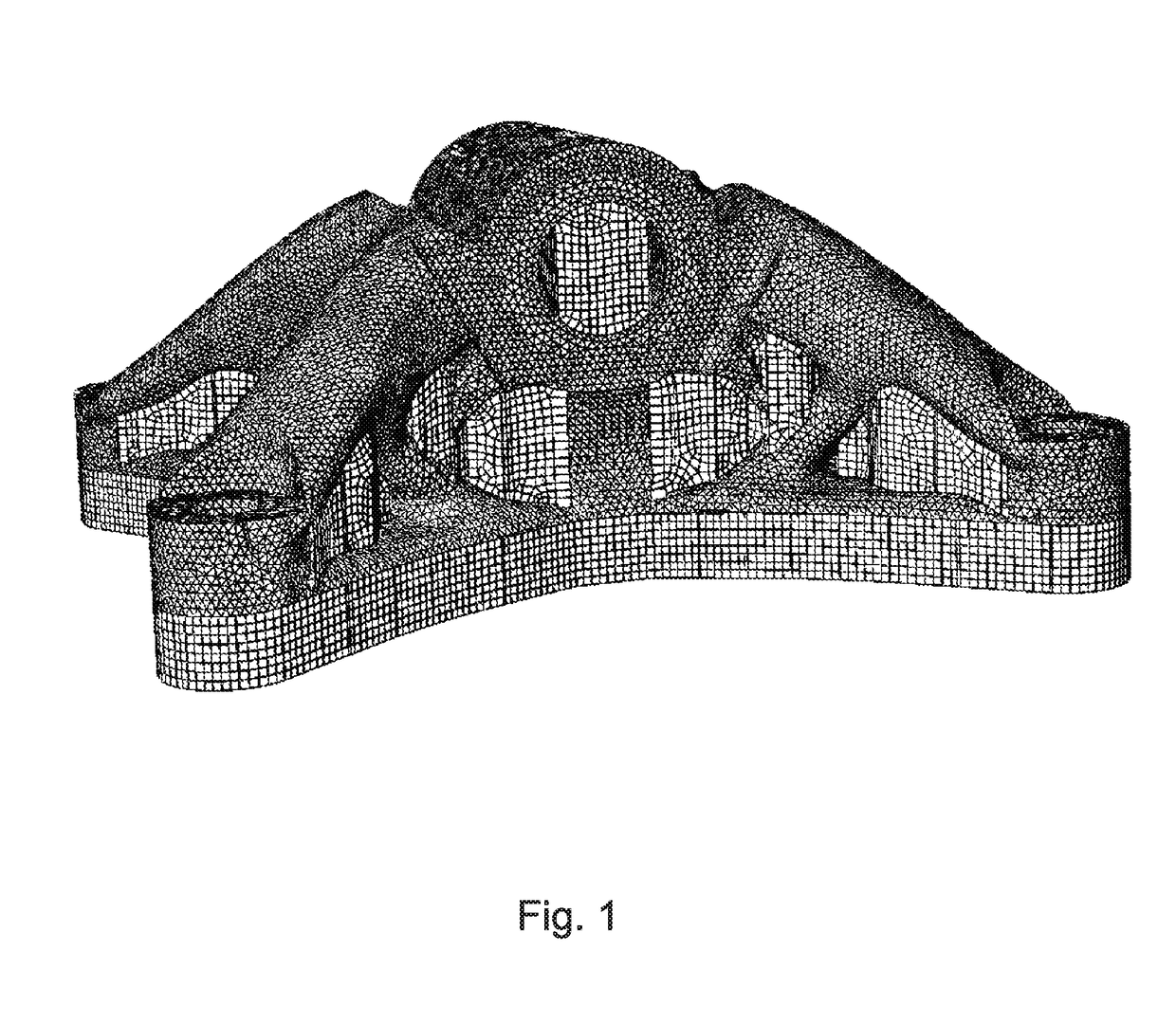
[0032]Meshing: The geometric shape of the part for which the 3D printing process is to be modeled is first discretized with finite elements. Arbitrary meshes can be used of arbitrary mesh densities. Using such meshes greatly improves on streamlining the analysis process as typically AM fabricated parts have VERY complex shapes for which uniform meshes are not really possible. An example of such a complex shape with arbitrary meshing is shown in FIG. 1

[0033]Machine information: Information related to a 3D printing machine (e.g., powder recoating sequence, laser scan path, material deposition of the printing head, etc.) that will be manufacturing the part is pre-processed with no loss of accuracy from actual data as use...


PUM

PropertyMeasurementUnit
Volumeaaaaaaaaaa
Surface areaaaaaaaaaaa
Heataaaaaaaaaa

Abstract

Methods and systems for providing accurate, scalable, and predictive 3D printing simulations using numerical methods for part-level simulations. Complex parts can be discretized into finite elements using independent and arbitrary meshing. The real additive manufacturing tooling path and printing time of a printing machine are simulated and applied to the mesh of finite elements using an intersection module that combines the finite element mesh with the tool path information of the printing machine in a geometric sense. This allows for localized heating effects to be simulated very accurately, and for cooling assessments to be precisely computed given the intersection module's computation of partial facets and volumes of the finite elements at any given time in the printing simulation.

Description

RELATED APPLICATION[0001]This application claims the benefit of U.S. Provisional Application No. 62 / 339,203, filed on May 20, 2016. The entire teachings of the above application are incorporated herein by reference.BACKGROUND[0002]The impetus of 3D printing technology in recent years is significant. Many printer manufacturers exist and new companies seem to appear overnight. Despite this wave of new developments, in many (if not most) cases, the reliability of the technology is limited, and printed, or additive manufactured (“AM”), parts suffer from defects that lead to subpar strength and fatigue life when compared to parts manufactured with conventional technologies. This negative aspect limits severely the spread of the technology. Computer simulations are sought to provide insight into the process so that progress in raising the quality of AM parts can be achieved.[0003]Many physics-related aspects of the additive manufacturing process are similar to some of the conventional man...

Claims


Application Information

Patent Timeline
IPC IPC(8): G06F17/50B33Y50/00
CPCB33Y50/00G06F17/5018G06F30/23B22F10/20B22F10/80G06F2111/10B33Y50/02Y02P10/25
Inventor OANCEA, VICTOR GEORGEHURTADO ORTIZ, JUAN ANTONIOENGELMANN, BRUCEGRIMES, WILLIAM JOHN
Owner DASSAULT SYSTEMES SIMULIA CORP
Why Eureka
Try Eureka