
System and method for detection of electrical faults in an electrical network

a technology of electrical faults and detection methods, applied in the field of system and method for detection of electrical faults in electrical networks, can solve problems such as short circuits, electrical fault detection, and fault detection

Active Publication Date: 2017-11-23
ISRA JUK ELECTRONICS
View PDF0 Cites 13 Cited by
  • Summary
  • Abstract
  • Description
  • Claims
  • Application Information

AI Technical Summary

Benefits of technology

The present invention is about a method and device for automatically and continuously monitoring and detecting electrical faults in an electrical device connected to an electrical network. The invention can detect faults before they cause a critical incident, which can be a safety or operational impact. The invention uses various parameters associated with voltage and current patterns to define the electrical behavior of the device or network at a particular point in the network. By monitoring and detecting these deviations from an acceptable electrical behavior, the invention can help prevent failures and improve safety in electrical devices and networks.

Problems solved by technology

Presently, faults can be detected only after the electrical fault caused a failure in the device, affected the electrical device or an electrical grid or net supplying power to the device.
For example, some electrical faults can be detected after a smell of burned polymer is spread in a space in close proximity to the failing device or electrical system.
Other electrical faults are detected after a fuse or an electrical circuit becomes damaged or burned.
Electrical fault can cause short circuit and spark that may in return start a fire.
The higher the amount of combustible material near by the spark—the higher is the chance that a fire will start.
For example, wood or timber houses are more flammable than brick houses, thus more sensitive to sparks.

Method used


Image

  • System and method for detection of electrical faults in  an electrical network
  • System and method for detection of electrical faults in  an electrical network
  • System and method for detection of electrical faults in  an electrical network

Examples


Embodiment Construction

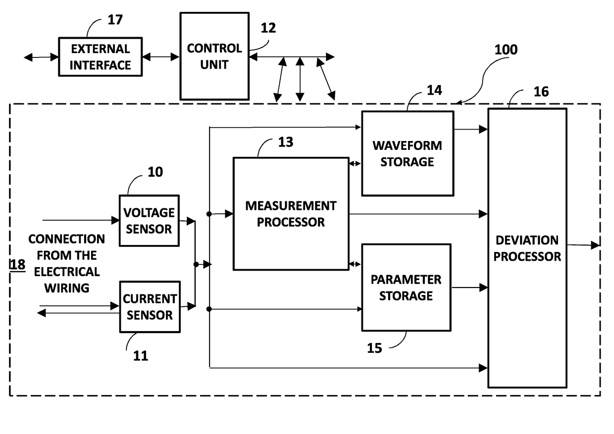
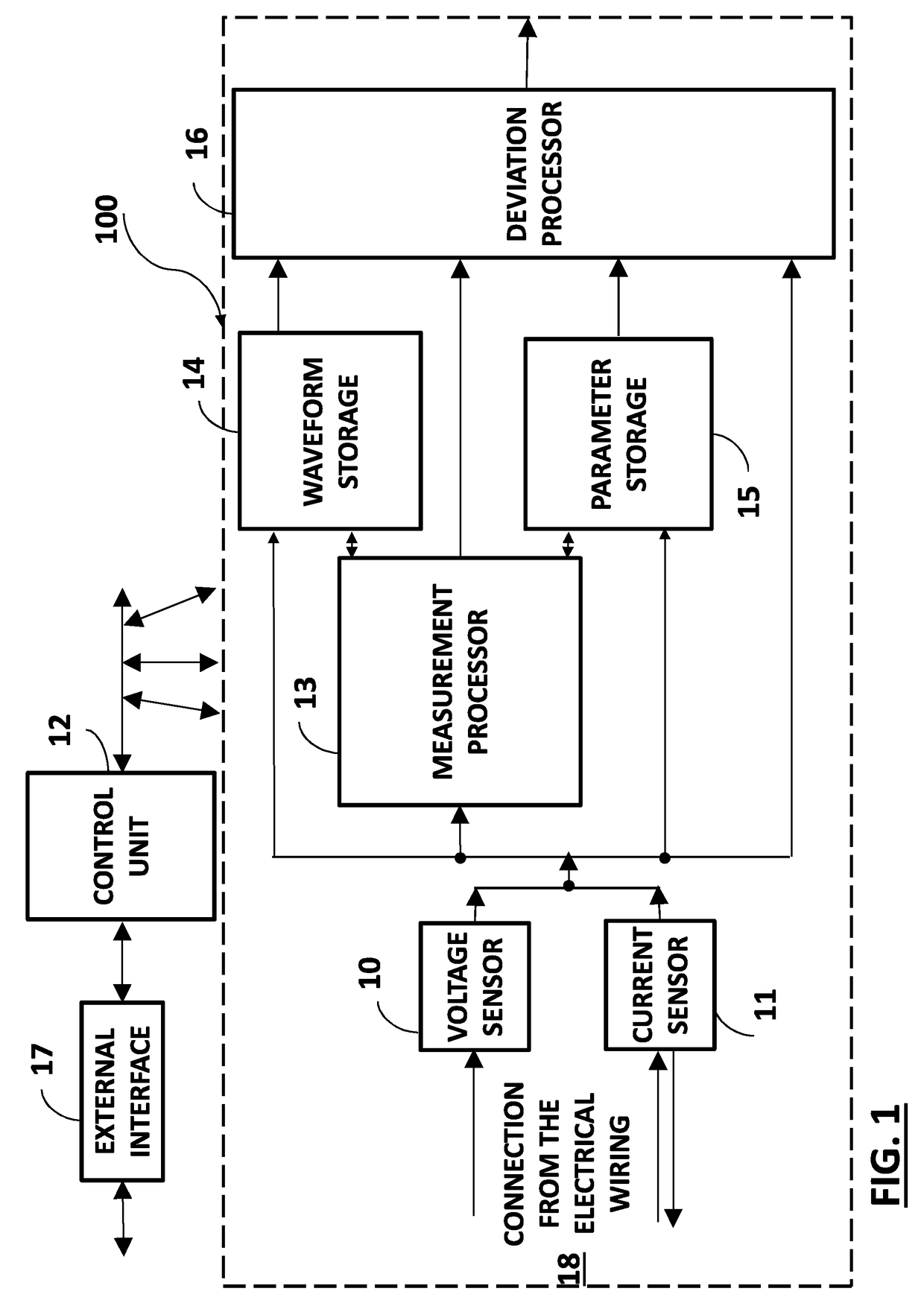
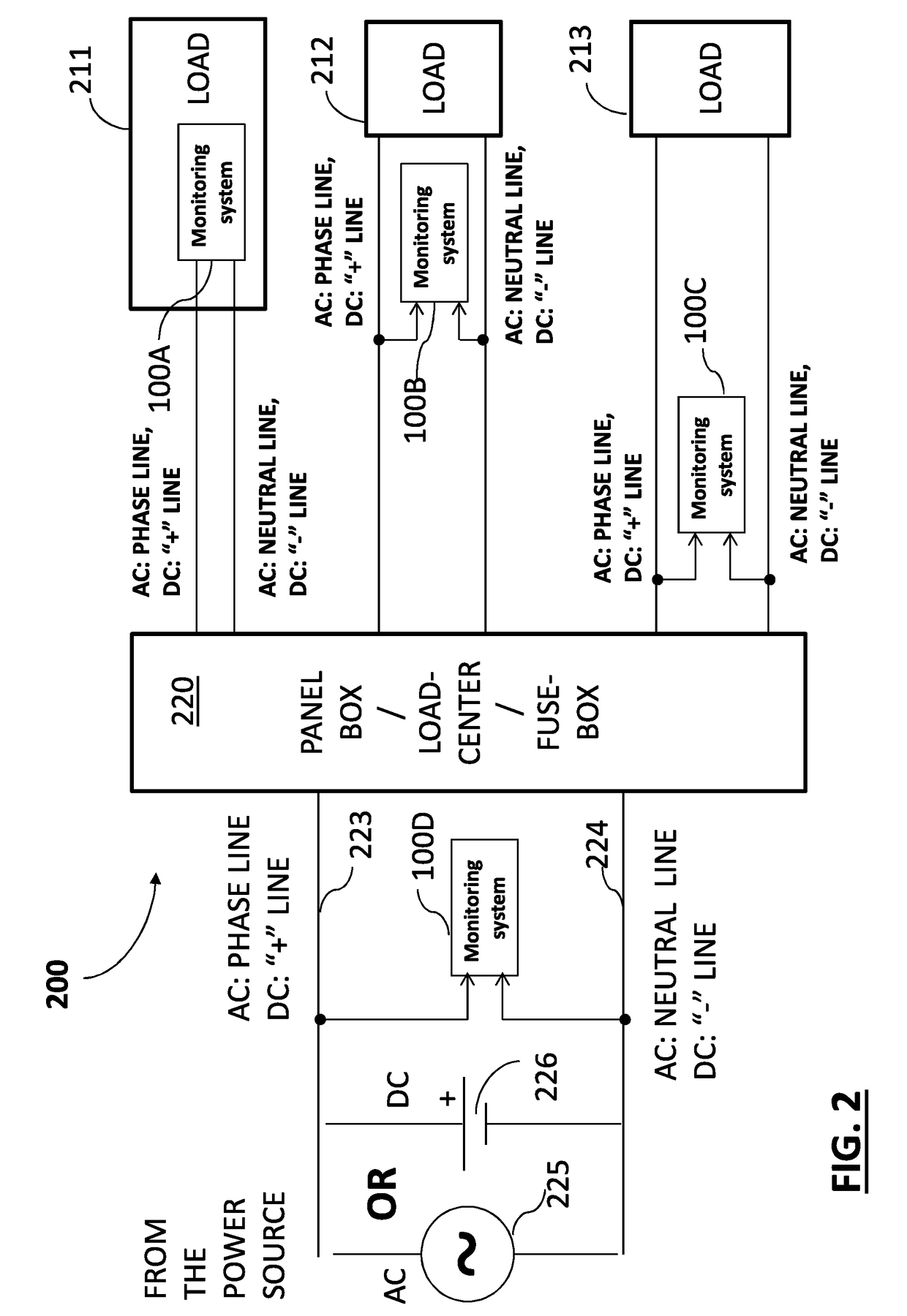
[0017]Some aspects of the present invention may be related to a method and a device for automatically and continuously monitoring and detecting electrical faults in an electrical device connected to an electrical network or in the electrical network itself (e.g., a grid or a distribution network). The electrical network may be connected to an external grid or power supply, for example, a power supplied by a utility company, or may be connected to an independent power source, for example, a battery in a car. According to aspects of the invention faults may be detected prior to the occurrence of a critical incident. A critical incident in an electrical device or an electrical network may be defined as any incident that may harm the device or the electrical network, for example, cause a spark, or may result in any other incident that may have a safety or operational impact.

[0018]Embodiments of the invention may be directed to automatically and continuously monitoring and detecting elec...


PUM


Abstract

A method and a system for detecting and processing one or more deviations from an acceptable electrical behavior at a point of interest in an electrical network, the system comprising a voltage sensor and / or a current sensor, a measurement-processor configured to process measurements received from the at least one of a voltage sensor and a current sensor, at least one storage for storing one or more acceptable values related to the electrical behavior at the point of interest, and a deviation-processor, the deviation processor is configured to receive one or more detected values related to the electrical behavior at a point in time at the point of interest and detect one or more deviations between the one or more acceptable values and the one or more detected values, and analyze one or more deviations between the one or more acceptable values and the one or more detected values.

Description

CROSS REFERENCE TO RELATED APPLICATIONS[0001]This application claims the benefit of GB Patent Application No. 1419377.5 filed on Oct. 31, 2014 which incorporated herein by reference in its respective entirety.BACKGROUND OF THE INVENTION[0002]Detecting faults in an electrical device or an electrical network has a major safety and preventive-maintenance impact, particularly detecting the faults before a critical incident has happened. Presently, faults can be detected only after the electrical fault caused a failure in the device, affected the electrical device or an electrical grid or net supplying power to the device. For example, some electrical faults can be detected after a smell of burned polymer is spread in a space in close proximity to the failing device or electrical system. Other electrical faults are detected after a fuse or an electrical circuit becomes damaged or burned. In yet another example, a fault can be detected when a fuse, circuit-breaker or plug included in a fu...

Claims


Application Information

Patent Timeline
IPC IPC(8): G01R19/165G01R31/50
CPCG01R19/16528H02H1/0092H02H3/38H02H3/50H02H7/22G01R19/2513H02H1/0007G01R31/50G01R17/00G01R19/165H02H3/00
Inventor SELA, ISAAC
Owner ISRA JUK ELECTRONICS
Learn More