
Piston having an undercrown surface with insulating coating and method of manufacture thereof

a technology of insulating coating and piston, which is applied in the direction of metal material coating process, machine/engine, coating, etc., can solve the problems of reducing engine fuel efficiency, and high operating temperature of pistons used in internal combustion engines, so as to reduce the tendency for cooling oil to be degraded, surface temperature and surface deposits

Active Publication Date: 2017-11-23
TENNECO INC
View PDF43 Cites 6 Cited by
  • Summary
  • Abstract
  • Description
  • Claims
  • Application Information

AI Technical Summary

Benefits of technology

This patent relates to a piston for an internal combustion engine that can reduce the surface temperature and surface deposits on its inner surface, which can help prevent damage to the engine's cooling oil. The invention achieves this by using a ceramic material that contains both zirconia stabilized by ceria and zirconia stabilized by yttria. The combination of these two stabilizers helps to reduce the tendency for degradation of the cooling oil.

Problems solved by technology

Pistons used in internal combustion engines, such as heavy duty diesel pistons, are exposed to extremely high temperatures during operation, especially along the crown of the piston.
However, to control the piston temperature during operation, a high flow of oil must be constantly maintained, which adds to the parasitic losses, which in turn reduces the engine fuel efficiency.
In addition, the oil degrades over time due to the high temperature of the internal combustion engine, and thus, the oil must be changed periodically to maintain adequate engine life.
Furthermore, when the piston cooling gallery and / or undercrown temperature is exposed to high temperatures over a prolonged period of time, the oil tends to coke at an increased rate, and resulting deposits of coked oil may buildup on the inner surface of the cooling gallery and / or on the undercrown.

Method used


Image

  • Piston having an undercrown surface with insulating coating and method of manufacture thereof
  • Piston having an undercrown surface with insulating coating and method of manufacture thereof
  • Piston having an undercrown surface with insulating coating and method of manufacture thereof

Examples


Embodiment Construction

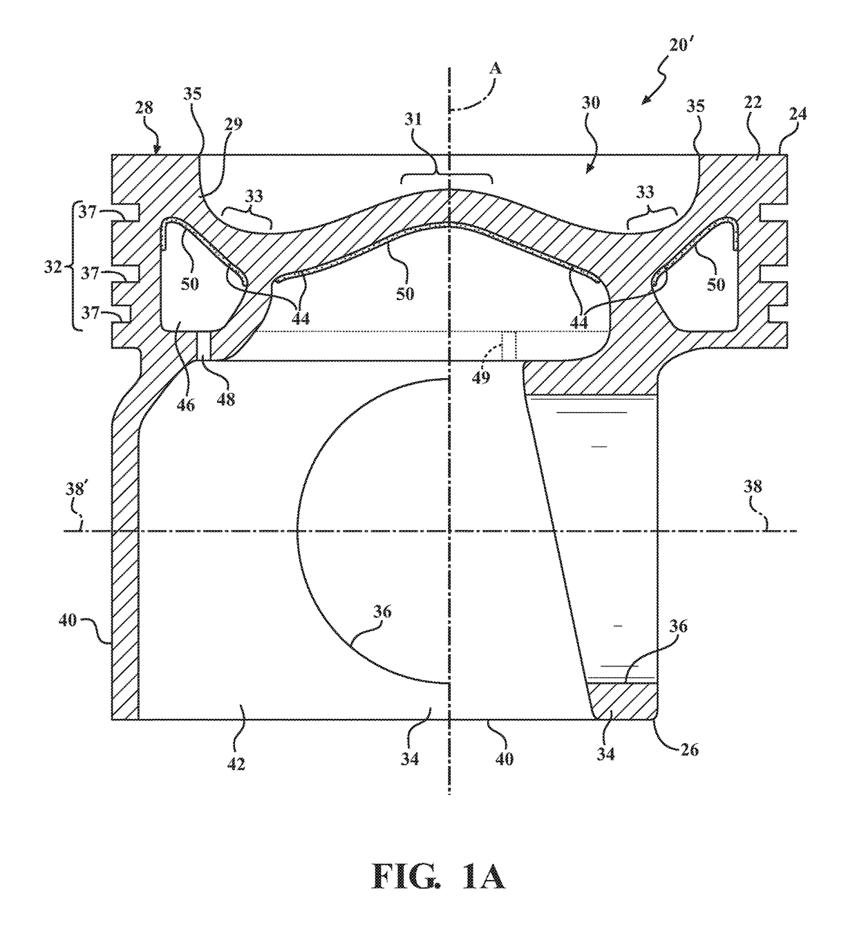
[0046]Referring in more detail the drawings, FIGS. 1, 1A-3 illustrate respective pistons 20, 20′, 20″, 20′″ for an internal combustion engine according to different example embodiments of the invention. The pistons 20, 20′, 20″, 20′″ are discussed hereafter using the same reference numerals to identify like features. The pistons 20, 20′, 20″, 20′″ each have a body 22 formed of a metal material, such as steel extending along a center axis A, along which the pistons 20, 20′, 20″, 20′″ reciprocate in use, from an upper end 24 to a lower end 26. The body 22 of the pistons 20, 20′, 20″, 20′″ include a crown 28 at the upper end 24 of an upper combustion wall 29, wherein the crown 28 is directly exposed to a combustion chamber and hot gases therein during use, with a combustion bowl 30 depending therein.

[0047]In the example embodiments, the combustion bowl 30 of the body 22 presents an apex region 31 about the center axis A, a concave, toroidal bowl-shaped valley region 33 surrounding the ...


PUM

PropertyMeasurementUnit
thermal conductivityaaaaaaaaaa
thicknessaaaaaaaaaa
thermal conductivityaaaaaaaaaa

Abstract

A vehicle internal combustion piston and method of construction thereof are provided. The piston includes piston body extending along a central longitudinal axis, having an upper combustion wall forming an upper combustion surface and an undercrown surface opposite the upper combustion surface. An annular ring belt region depends from the upper combustion surface, a pair of skirt panels depend from the ring belt region, and a pair of pin bosses depend from the undercrown surface to provide laterally spaced pin bores aligned along a pin bore axis for receipt of a wrist pin. The undercrown surface forms a central undercrown surface, and a portion of either an open outer cooling gallery, a sealed outer cooling gallery, or an outer galleryless region, wherein an insulating coating is applied to at least one of the portions of the undercrown surface.

Description

CROSS-REFERENCE TO RELATED APPLICATION[0001]This application claims the benefit of U.S. Provisional Application Ser. No. 62 / 339,053, filed May 19, 2016, which is incorporated herein by reference in its entirety.BACKGROUND OF THE INVENTION1. Field of the Invention[0002]This invention relates generally to pistons for internal combustion engines, and methods for manufacturing the pistons.2. Related Art[0003]Pistons used in internal combustion engines, such as heavy duty diesel pistons, are exposed to extremely high temperatures during operation, especially along the crown of the piston. Engine and piston manufacturers typically attempt to control the temperature of the crown and reduce heat loss from the combustion chamber to the crown, in order to maintain usable fuel energy and high gas temperature inside the combustion chamber, and to achieve a higher engine break thermal efficiency (BTE).[0004]To moderate the temperature of the crown, some pistons are designed with a cooling galler...

Claims


Application Information

Patent Timeline
Patent Type & Authority Applications(United States)
IPC IPC(8): F02F3/10C23C30/00F02F3/00F02F3/18
CPCF02F3/10F02F3/0069F02F2200/00C23C30/00F02F3/18F05C2251/048
Inventor MATSUO, EDUARDOLINETON, WARRAN BOYD
Owner TENNECO INC
Learn More