
Piezoelectric fiber having excellent flexibility and elasticity, and method for manufacturing the same

a technology of piezoelectric fiber and elasticity, which is applied in the field of piezoelectric fiber, can solve the problems of low efficiency per unit area, too large to carry, and difficult to manufacture, and achieves excellent piezoelectricity and durability, excellent flexibility, and sufficient elasticity

Active Publication Date: 2017-11-16
IUCF HYU (IND UNIV COOP FOUNDATION HANYANG UNIV)
View PDF11 Cites 29 Cited by
  • Summary
  • Abstract
  • Description
  • Claims
  • Application Information

AI Technical Summary

Benefits of technology

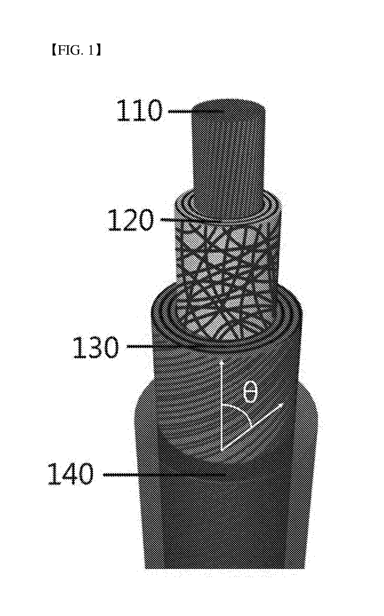
The present invention relates to a piezoelectric fiber that has excellent flexibility and can be used in various wearable electronic devices, portable devices, clothing, etc. The piezoelectric fiber has a conductive fiber member as an inner electrode, on which a piezoelectric polymer layer, an outer electrode and a coating layer are sequentially formed. The piezoelectric fiber can effectively convert deformation or vibration caused by external physical force into electric energy, thus replacing existing ceramic-based and polymer piezoelectric bodies. The present invention also provides an economical and simple method of manufacturing a piezoelectric fiber having excellent piezoelectricity.

Problems solved by technology

Conventionally, as portable power supplies, chemical cells or rechargeable batteries have been used, and they can cause serious environmental pollution when they are disposed of.
To avoid this problem, devices that can use natural energy produced from wind power, geothermy, solar heat, or wave power, etc. as electric energy and can provide environmentally friendly power have been developed, but they are too big to carry.
Further, since these devices are highly influenced by the environment, they have low efficiency per unit area.
However, these piezoelectric energy harvesters exhibit low flexibility and elasticity and thus are difficult to fabricate into clothing or fabrics having complicated structures, and their efficiency at converting motion of the human body into electric energy is significantly low.
However, because these two energy harvesters also employ piezoelectric ceramics, which generally serve as metallic electrodes, they still have low flexibility and elasticity, and thus are limited to the structure of cloth.(Patent Document 1) KR patent publication 10-2014-0073201(Patent Document 2) KR patent publication 10-2012-0083261(Non-patent Document 1) M. B. Lee, C. Y. Chen, S. W. Cha, Y. J. Park, J. M. Kim, L. J. Chou, Z. L. Wang, Adv. Mater. 2012, 24, 1759(Non-patent Document 2) M. B. Kechiche, F. Bauer, O. Harzallah, J. Y. Drean, Sensors and Actuators A.

Method used


Image

  • Piezoelectric fiber having excellent flexibility and elasticity, and method for manufacturing the same
  • Piezoelectric fiber having excellent flexibility and elasticity, and method for manufacturing the same
  • Piezoelectric fiber having excellent flexibility and elasticity, and method for manufacturing the same

Examples


example 1

[0110]1) Manufacture of Two-Dimensional PVDF-TrFE Mat:

[0111]1.5 g of PVDF-TrFE was mixed with 2.55 g of dimethylacetamide and 5.96 g of acetone to prepare a 15 wt % PVDF-TrFE solution (70:30, Piezotech, France). After being stirred for 24 hrs at room temperature, the resulting PVDF-TrFE solution was applied to an electrospinning device which was equipped with a high-voltage DC power supply (Wookyung Tech Co., Ltd., Korea) and composed of a syringe needle (15 kV) and an aluminum foil collector (˜5 kV) spaced 20 cm from the needle. In consideration of the voltage between these components, a voltage of 20 kV was applied. While the PVDF-TrFE solution was fed at a speed of 4 μl / min with the aid of a syringe pump, a PVDF-TrFE mat was manufactured on the aluminum foil. The PVDF-TrFE mat was cut into rectangular pieces (1 cm×10 cm) before use.

[0112]2) Manufacture of One-Dimensional PVDF-TrFE Fiber:

[0113]Silver-coated nylon (PN#260151011717, 117 / 17 2ply, StatexShieldex, USA) was placed on an...

example 2

[0119]A piezoelectric fiber in a twisted structure was manufactured using the piezoelectric fiber prepared in Example 1.

[0120]One end of the piezoelectric fiber prepared in Example 1 was connected to a rotation motor and the other end was fixed to a 26 g weight. The rotation motor was operated at a speed of 2,000 twists / m to manufacture the piezoelectric fiber in a coil structure. The coil-shaped piezoelectric fiber finally obtained had a diameter of 550 μm.

[0121]The piezoelectric fiber with a coiled structure obtained through the twisting process was shortened from an initial length of 4.3 cm to 1.2 cm. The piezoelectric fiber with a coiled structure was measured to respective resistances of 20 Ω / cm and 1.3 kΩ / cm for the inner electrode and the outer electrode.

[0122]Given an external load, the force per unit area (P, stress) of the piezoelectric fiber prepared in Example 1 can be calculated according to the following Equation 1:

P=1T∫U2(t)Rdt[Equation1]

[0123]wherein,

[0124]U(t) is a ...


PUM


Abstract

The present invention relates to a piezoelectric fiber having excellent flexibility, the piezoelectric fiber employs a conductive fiber member as an inner electrode, on which a piezoelectric polymer layer, an outer electrode and a coating layer are sequentially formed, thereby having excellent flexibility and sufficient elasticity to be sewed, woven, knotted or braided. Therefore, the piezoelectric fiber can be applied in power supplies for a variety of sizes and types of wearable electronic devices, portable devices, clothing, etc. In addition, since the piezoelectric fiber has excellent piezoelectricity and durability because of the above-described structure, it can effectively convert deformation or vibration caused by external physical force into electric energy, and thus can replace existing ceramic-based and polymer piezoelectric bodies, etc. Furthermore, an economical and simple method of manufacturing a piezoelectric fiber having excellent piezoelectricity is provided.

Description

TECHNICAL FIELD[0001]The present invention relates to a piezoelectric fiber and a manufacturing method thereof, and more particularly, to a piezoelectric fiber having excellent flexibility and elasticity, and a method of manufacturing the same.BACKGROUND ART[0002]In recent years, with the development of human clothing and various wearable portable electronic devices such as wearable computers, smart wear, etc., there has been a sharp rise in the demand for portable power supplies that can be driven for a long time and are slim and light enough to minimize the burden of carrying them.[0003]Conventionally, as portable power supplies, chemical cells or rechargeable batteries have been used, and they can cause serious environmental pollution when they are disposed of.[0004]To avoid this problem, devices that can use natural energy produced from wind power, geothermy, solar heat, or wave power, etc. as electric energy and can provide environmentally friendly power have been developed, bu...

Claims


Application Information

Patent Timeline
IPC IPC(8): H01L41/08H01L41/257H01L41/33H01L41/35
CPCH01L41/082H01L41/35H01L41/257H01L41/33H10N30/60H10N30/03H10N30/857H10N30/098H10N30/702H10N30/01H10N30/08H10N30/09H10N30/045
Inventor KIM, SEONJEONGSIM, HYEONJUN
Owner IUCF HYU (IND UNIV COOP FOUNDATION HANYANG UNIV)
Learn More