
Light-emitting module

a technology of light-emitting modules and modules, applied in the field of light-emitting modules, to achieve the effect of reducing the hot spot mura and reducing the energy in the area

Active Publication Date: 2017-11-16
E INK HLDG INC
View PDF9 Cites 5 Cited by
  • Summary
  • Abstract
  • Description
  • Claims
  • Application Information

AI Technical Summary

Benefits of technology

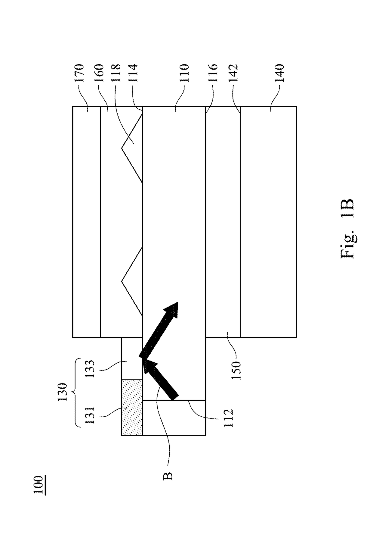
The present invention describes a light guide plate for a display that can evenly distribute light energy to each position of the visual area, to decrease hot spot mura. The invention includes a brightness adjustment element that absorbs the light of the high energy area in front of the light source to avoid light area being generated in an area of the light guide plate in front of the light source. Additionally, a microstructure region on the front surface or the back surface of the light guide plate can destroy the total reflection of the light to make the light refract at and exit from the microstructure region, thus avoid light area being generated in an area of the light guide plate in front of the light source. These features improve the assembly convenience and brightness uniformity of the light guide plate.

Problems solved by technology

However, the LED is a point source, which may generate a hot spot while applying in a light-emitting module, so as to cause a nonuniform brightness at a side frame of the display device.

Method used


Image

  • Light-emitting module
  • Light-emitting module
  • Light-emitting module

Examples


Embodiment Construction

[0083]The embodiments of the transparent heat-conducting structure and a method for manufacturing the same of the present disclosure are discussed in detail below, but not limited the scope of the present disclosure. The same symbols or numbers are used to the same or similar portion in the drawings or the description. And the applications of the present disclosure are not limited by the following embodiments and examples which the person in the art can apply in the related field.

[0084]The singular forms “a,”“an” and “the” used herein include plural referents unless the context clearly dictates otherwise. Therefore, reference to, for example, a metal layer includes embodiments having two or more such metal layers, unless the context clearly indicates otherwise. Reference throughout this specification to “one embodiment” means that a particular feature, structure, or characteristic described in connection with the embodiment is included in at least one embodiment of the present discl...


PUM


Abstract

The present disclosure provides a light-emitting module. The light-emitting module includes a light guide plate, a light source, and a brightness adjustment element. The light guide plate has a light incident surface, a front surface, and a back surface opposite the front surface. The light incident surface is located between the front surface and the back surface and is adjacent to the front surface and the back surface. The brightness adjustment element has a strip portion and at least one protruding portion. The strip portion has a first edge proximal to the light incident surface. The protruding portion is located on the first edge of the strip portion, and the protruding portion is aligned with the light source and extends away from the first edge.

Description

RELATED APPLICATIONS[0001]This application is a Continuation-in-part of U.S. application Ser. No. 14 / 540,042, filed on Nov. 13, 2014, which claims priority of Taiwan Patent Application Serial Number 103103617, filed on Jan. 29, 2014, and this application claims priority to China Application Serial Number 201710226954.8, filed on Apr. 7, 2017, and China Application Serial Number 201710222786.5, filed on Apr. 7, 2017, the entirety of which is incorporated by reference herein.BACKGROUNDTechnical Field[0002]The present disclosure relates to a light-emitting module, and more particularly, to a light-emitting module having a light-adjusting film.Description of Related Art[0003]In a conventional display device, a light-emitting module is indispensable. The light-emitting module is usually composed of a light guide plate, a light source and a light-blocking strip. The light source emits light toward a light-entering surface of the light guide plate, and the light may be uniformly extracted ...

Claims


Application Information

Patent Timeline
Patent Type & Authority Applications(United States)
IPC IPC(8): F21V8/00
CPCG02B6/0036G02B6/0083G02B6/0031G02B6/0093G02B6/0068G02B6/0016
Inventor SHIH, YAO-TSUNGCHANG, MEI-CHENPAO, YU-NANHUANG, HSIN-TAO
Owner E INK HLDG INC
Learn More