External cavity laser with reduced optical mode-hopping

Active Publication Date: 2017-11-09
ORACLE INT CORP
View PDF6 Cites 17 Cited by
  • Summary
  • Abstract
  • Description
  • Claims
  • Application Information

AI Technical Summary

Benefits of technology

The present patent describes an optical source that includes a semiconductor optical amplifier and a reflective coating on its edge. The amplifier provides an optical signal at the other edge of the amplifier. The optical source also includes a photonic chip with an optical waveguide and a ring resonator, which reflects the optical signal and measures its power. A thermal-tuning mechanism adjusts the resonance wavelength of the ring resonator to lock the optical signal to a carrier wavelength. The optical source can be edge-coupled or surface-normal coupled to the photonic chip. The system includes a processor, memory, and the optical source. The method includes generating the optical signal in the semiconductor optical amplifier, conveying it in the optical waveguide, and measuring its power using the ring resonator. The temperature of the ring resonator is modified to adjust the carrier wavelength. The technical effects of this patent include improved optical signal generation and stabilization.

Problems solved by technology

However, tunable silicon photonic reflectors are often very sensitive to temperature changes.
During data transmission, wavelength optical mode-hops are essentially ‘glitches’ that can corrupt data transmitted, or may send data to the incorrect destination in a wavelength-division-multiplexed (WDM) system.
Consequently, optical mode-hopping is undesirable for digital communication links and typically needs to be reduced before a tunable hybrid external cavity laser may be effectively used for transmitting high-speed data across a range of wavelengths with good fidelity across the communication channel.

Method used


Image

  • External cavity laser with reduced optical mode-hopping
  • External cavity laser with reduced optical mode-hopping
  • External cavity laser with reduced optical mode-hopping

Examples


Embodiment Construction

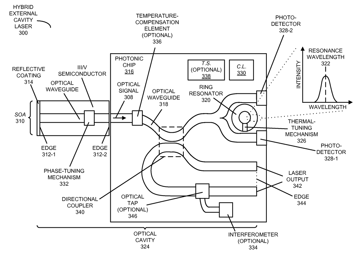
[0029]Embodiments of a hybrid external cavity laser, a system that includes the hybrid external cavity laser, and a technique for locking a cavity mode for an external cavity laser are described. The hybrid external cavity laser includes a semiconductor optical amplifier (with a semiconductor other than silicon) that provides an optical gain medium and that includes a reflector (such as a mirror). Moreover the hybrid external cavity laser includes a photonic chip with: an optical waveguide that conveys an optical signal output by the semiconductor optical amplifier; and a ring resonator (as a wavelength-selective filter), having a resonance wavelength, which reflects at least a resonance wavelength in the optical signal, where the reflector and the ring resonator define an optical cavity. Furthermore, the photonic chip includes: a thermal-tuning mechanism that adjusts the resonance wavelength; a photo-detector that measures an optical power output by the ring resonator; and control ...


PUM


Abstract

An optical source is described. This optical source includes a semiconductor optical amplifier (with a semiconductor other than silicon) that provides an optical gain medium and that includes a reflector. Moreover the hybrid external cavity laser includes a photonic chip with: an optical waveguide that conveys an optical signal output by the semiconductor optical amplifier; and a ring resonator, having a resonance wavelength, which reflects at least a resonance wavelength in the optical signal, where the reflector and the ring resonator define an optical cavity. Furthermore, the photonic chip includes: a thermal-tuning mechanism that adjusts the resonance wavelength; a photo-detector that measures an optical power output by the ring resonator; and control logic that adjusts the temperature of the ring resonator based on the measured optical power to lock a cavity mode of the optical cavity to a carrier wavelength.

Description

CROSS-REFERENCE TO RELATED APPLICATION[0001]This application claims priority under 35 U.S.C. §119(e) to U.S. Provisional Application Ser. No. 62 / 068,453, entitled “Tunable External-Cavity Silicon-Assisted Laser With Minimized Mode-Hopping,” by Ashok V. Krishnamoorthy and Xuezhe Zheng, Attorney Docket No. ORA15-0239PSP, filed on Oct. 24, 2014, the contents of which are herein incorporated by reference.GOVERNMENT LICENSE RIGHTS[0002]This invention was made with U.S. Government support under Agreement No. HR0011-08-9-0001 awarded by DARPA. The U.S. Government has certain rights in the invention.BACKGROUNDField[0003]The present disclosure relates to the design of an optical source. More specifically, the present disclosure relates to the design of an external cavity laser with reduced optical mode-hopping.Related Art[0004]A hybrid external cavity laser often includes a III-V material section as an electrically pumped optical gain medium, and a silicon minor as the other reflector in the...

Claims


Application Information

Patent Timeline
IPC IPC(8): H01S5/14H01S5/068H01S5/00H01S5/065H01S5/50H01S5/10
CPCH01S5/141H01S5/50H01S5/10H01S5/005H01S5/0653H01S5/06804H01S3/083H01S5/0612H01S5/06255H01S5/0654H01S5/0687H01S5/142H01S3/0637H01S3/10H01S3/10069H01S5/021H01S5/026H01S5/0262H01S5/065H01S5/06837H01S5/4068
Inventor KRISHNAMOORTHY, ASHOK V.LEE, JIN-HYOUNGZHENG, XUEZHE
Owner ORACLE INT CORP
Why Eureka
Try Eureka