
Apparatus and Method for Measuring Drilling Parameters of a Down-the-Hole Drilling Operation for Mineral Exploration

a drilling operation and measurement method technology, applied in the field of apparatus and a measurement method of drilling parameters of a drilling operation for mineral exploration, can solve the problems of largely inaccurate estimation of wob measurement when measured, hole tightening, and bit to ‘weld’ to the bottom of the hole, etc., and achieve the effect of accurate measuremen

Pending Publication Date: 2017-11-09
GLOBALTECH CORP PTY LTD
View PDF13 Cites 5 Cited by
  • Summary
  • Abstract
  • Description
  • Claims
  • Application Information

AI Technical Summary

Benefits of technology

The present invention provides an apparatus and method for accurately measuring rock drilling parameters for mineral exploration. This allows for better understanding and control during drilling operations. The apparatus is easy to use, cost-effective, and reliable for mineral exploration purposes.

Problems solved by technology

This measurement technique involves several estimations and assumptions and is therefore inaccurate.
For example:If torque increases abnormally or higher than expected, for assumed conditions, the hole may be tightening because of expanding clays or accumulation of cuttings.
If reducing of cooling fluid is overdone, excessive load or inadequate cooling could cause the bit to ‘weld’ to the bottom of the hole.
A largely inaccurate estimate of WOB measurement is obtained when measured at the surface because of the number of unaccounted and unknown factors.
Like WOB estimate, the torque on bit estimated at the surface is also grossly inaccurate because of several unaccounted and unknown factors.
This not only increases costs but also exacerbates the difficulty of training new drillers to operate the drilling equipment.
These problems are enlarged because of gross inaccuracies in WOB and torque measured at the surface.
However, these systems are not readily adaptable to mineral exploration because they are expensive, complicated, large, and are designed to be operated under different conditions.
Therefore, the bulky systems available for oil and gas exploration are not useable for down-the-hole drilling for mineral exploration.
Furthermore the complexity of equipment required for measurements in drilling for oil and gas and the associated costs are not justified in drilling for mineral exploration.

Method used


Image

  • Apparatus and Method for Measuring Drilling Parameters of a Down-the-Hole Drilling Operation for Mineral Exploration
  • Apparatus and Method for Measuring Drilling Parameters of a Down-the-Hole Drilling Operation for Mineral Exploration
  • Apparatus and Method for Measuring Drilling Parameters of a Down-the-Hole Drilling Operation for Mineral Exploration

Examples


first embodiment

[0119]Module 10

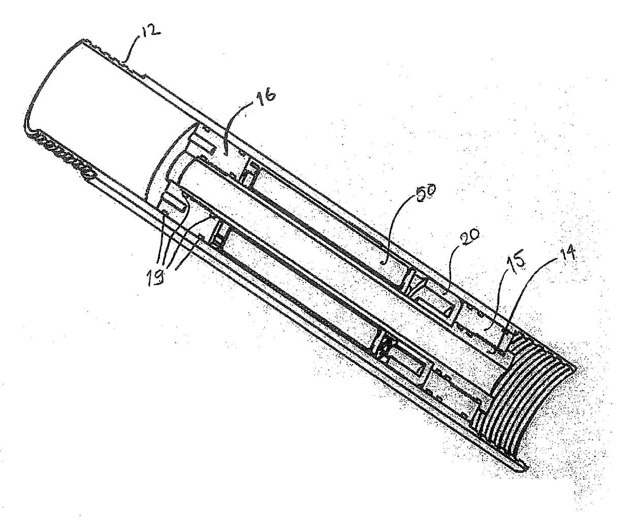
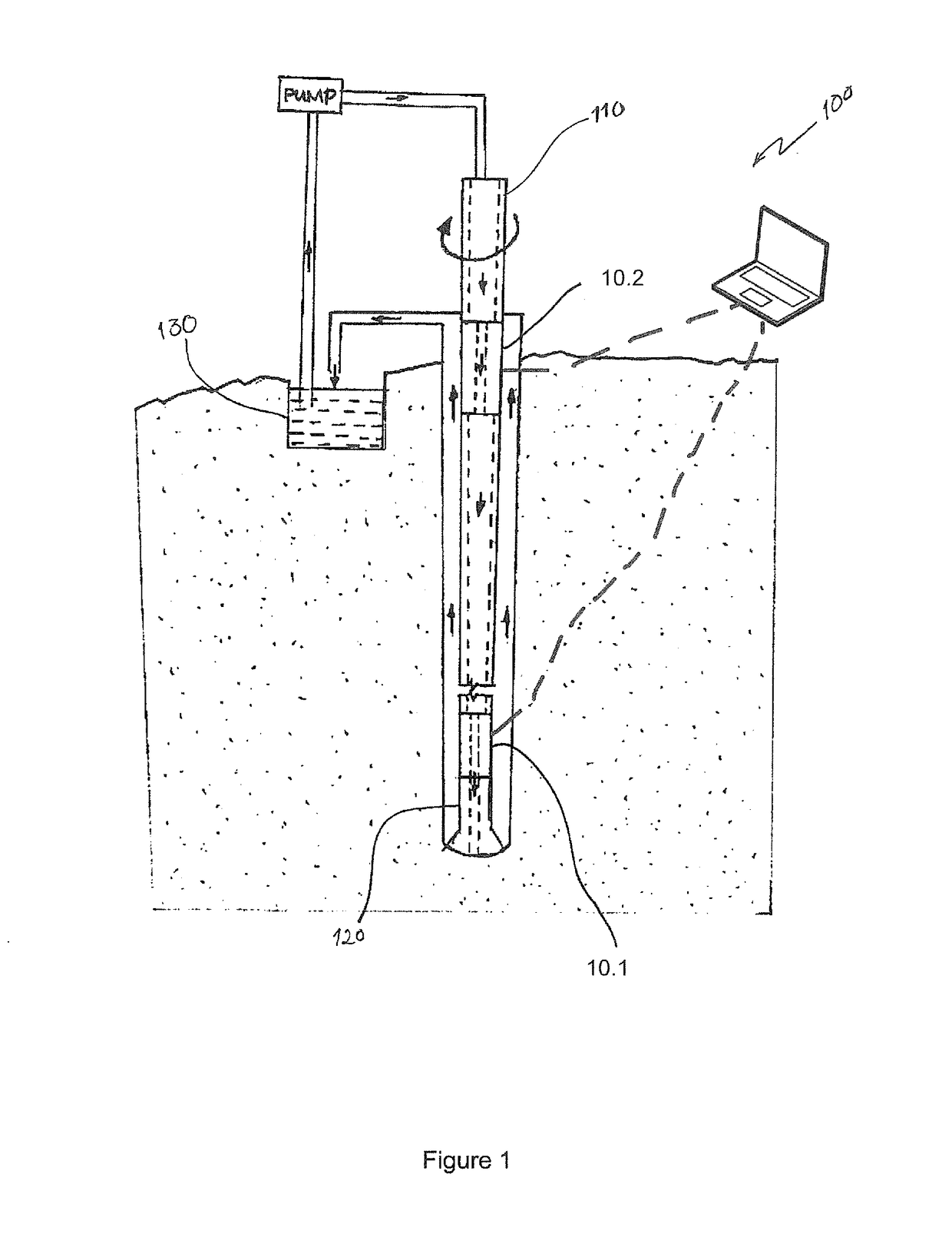
[0120]The module 10 has to operate in very harsh conditions. Drilling fluids 130, such as compressed air, water, or mud, are pumped through the drill string 110 and the module 10 to the drill bit 120 face to act as a cooling media. Drill cuttings are pushed out from between the drill string 110 and the hole by the drilling fluids 130. Since drilling fluids are recirculated, the drilling fluids 130 being pumped through the drill string include abrasive drill cuttings.

[0121]Further, the drilling fluids 110 may include extremely corrosive elements such as additives or ground water. The module 10 bears abrasion from the incoming and outgoing mixture of drilling fluids and drill cuttings. In addition, the drill bit 120 may drill holes having depths in excess of 1.5 km. Some drilling muds have specific gravity as high as 1.5 which increase the resultant ambient pressure around the drill bit to about 225 Bars (3400 psi).

[0122]The module 10 is designed to withstand these hars...

second embodiment

[0189]Module 10B

[0190]The following description is limited to the distinctive features of the module 10b of the second embodiment as compared to the module 10 as per the first embodiment, to avoid repetition.

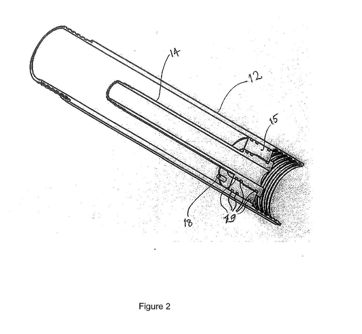
[0191]Referring to FIGS. 10 to 13, in a second embodiment the module 10b includes a load cell 70b mounted in the outer tube 12b. The load cell 70b comprises a first end cap 15b, an electronics sub-assembly 50b, a second end cap 16b, and a carrier 24b of strain gauges.

[0192]The electronics sub-assembly 50b has the electrical / electronics components such as mother board 60b (having some sensors, processor and memory), RF antenna 58b, and battery.

[0193]The first end cap 15b, the electronics sub-assembly 50b, and the second end cap 16b are mounted on the inner pipe 14b (not shown).

[0194]The carrier 24b is a flexible metal shim of rectangular shape. The carrier 24b is sized such that when positioned on the cylindrical assembly of the electronics sub-assembly 50b and the two end caps 1...


PUM


Abstract

Apparatus (100) for measuring drilling parameters of a down-the-hole drilling operation for mineral exploration includes a module 10.1 mounted in-line with a drill string (110) and proximate to a drill bit (120). The drill string (110) is rotated and progressed down the hole. The module (10) has sensors for sensing conditions. The apparatus (100) measures drilling parameters based on the sensed conditions. The measured data is logged in the module (10) and then transmitted to a computer for a drilling operator's use. The drilling operator monitors progress and optimises performance of the drilling operation based on the measured data. Measurement of drilling parameters based on sensed data proximate to the drill bit enables accurate determination of actual WOB, torque and RPM fluctuations, axial vibration, radial vibration, temperature, RPM. A second module 10.2 is mounted in-line with the same drill string (110) but away from the drill bit (120). The second module 10.2 measures the same drilling parameters as the module 10.1 proximate to the drill bit (120). The driller is provided with the data recorded by the second module 10.2 to judge the performance of the drilling operation. Comparing drilling parameters based on sensed data proximate to the drill bit and distal to the drill bit enables accurate determination of vertical drag / resistance of the drill string (110) within the hole, rotational resistance of the drill string (110), degree of wind-up of the drill string (110) and presence of stick-slip conditions at lower end of the drill string (110).

Description

FIELD OF THE INVENTION[0001]The present invention relates to an apparatus and a method for measuring drilling parameters of a down-the-hole drilling operation for mineral exploration.BACKGROUND TO THE INVENTION[0002]Mineral exploration is the process of finding commercially viable concentrations of minerals to mine. Drilling is often conducted as a part of an advanced exploration program to obtain detailed information about the rocks below the ground surface. The drilling method and size of the drilling rig used depends on the type of rock and information sought.[0003]A number of drilling techniques are used in the mineral exploration industry. Some of these are air-core drilling, reverse-circulation (RC) drilling, diamond core drilling, and rotary mud drilling.[0004]Air-core drilling employs hardened steel or tungsten blades to bore a hole into unconsolidated ground. The drill bit generally has three blades. Drill rods are hollow and are fitted with an inner tube within the outer b...

Claims


Application Information

Patent Timeline
IPC IPC(8): E21B47/00E21B47/01E21B45/00E21B47/12E21B47/06
CPCE21B47/0006E21B47/065E21B47/011E21B47/12E21B45/00E21B47/00E21B44/00E21B47/017E21B47/007E21B47/07
Inventor STEWART, GORDONHILL, RAYMOND
Owner GLOBALTECH CORP PTY LTD
Learn More