
Brushless wiper motor

Active Publication Date: 2017-11-02
MITSUBA CORP
View PDF4 Cites 7 Cited by
  • Summary
  • Abstract
  • Description
  • Claims
  • Application Information

AI Technical Summary

Benefits of technology

The present invention provides a brushless wiper motor that reduces the manufacturing cost of the stator while ensuring the sufficient coupling strength between the housing and the stator. This is achieved by using a pressing claw formed on the outer periphery of the stator, which absorbs a variation of the press-fitting load depending on the dimensional tolerance of the stator and reduces the press-fitting load of the stator to the housing. The tip end portions of the pressing claws are directed in the circumferential direction of the stator and improve the strength of coupling of the start to the housing, preventing the stator from rotating relative to the housing. This prevents the inner peripheral surface of the motor housing unit from being scraped by the stator and ensures the sufficient coupling strength between the housing and the stator.

Problems solved by technology

However, since the housing is made out of aluminum (low hardness), when the stator made of stacked steel sheets (high hardness) is pressed into an inner peripheral surface of the housing, the housing may be scraped by the stator, and scraped debris tends to be leaved inside the motor as foreign matter.
In the conventional technique described above, which can reduce the press-fitting load of the stator to the housing, since the ribs lack flexibility and fail to sufficiently reduce the press-fitting load, the inner peripheral surface of the housing made out of aluminum tends to be scraped by the stator, and the press-fitting load varies widely depending on dimensional tolerance of the stator.
A coupling strength between the housing and the stator varies widely depending on a product-by-product basis, which leads to lower yield.
This case, however, encounters a problem that the coupling strength between the housing and the stator becomes insufficient, and manufacturing cost of the stator increases.

Method used


Image

  • Brushless wiper motor
  • Brushless wiper motor
  • Brushless wiper motor

Examples


first embodiment

[0036]Hereinafter, the present invention will be described with reference to the drawings.

second embodiment

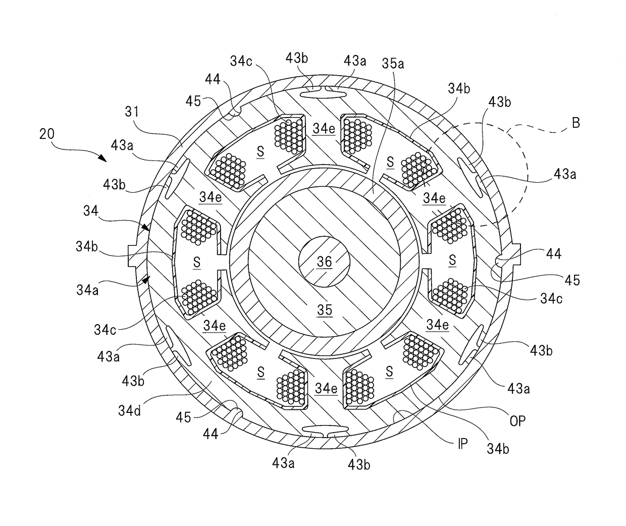
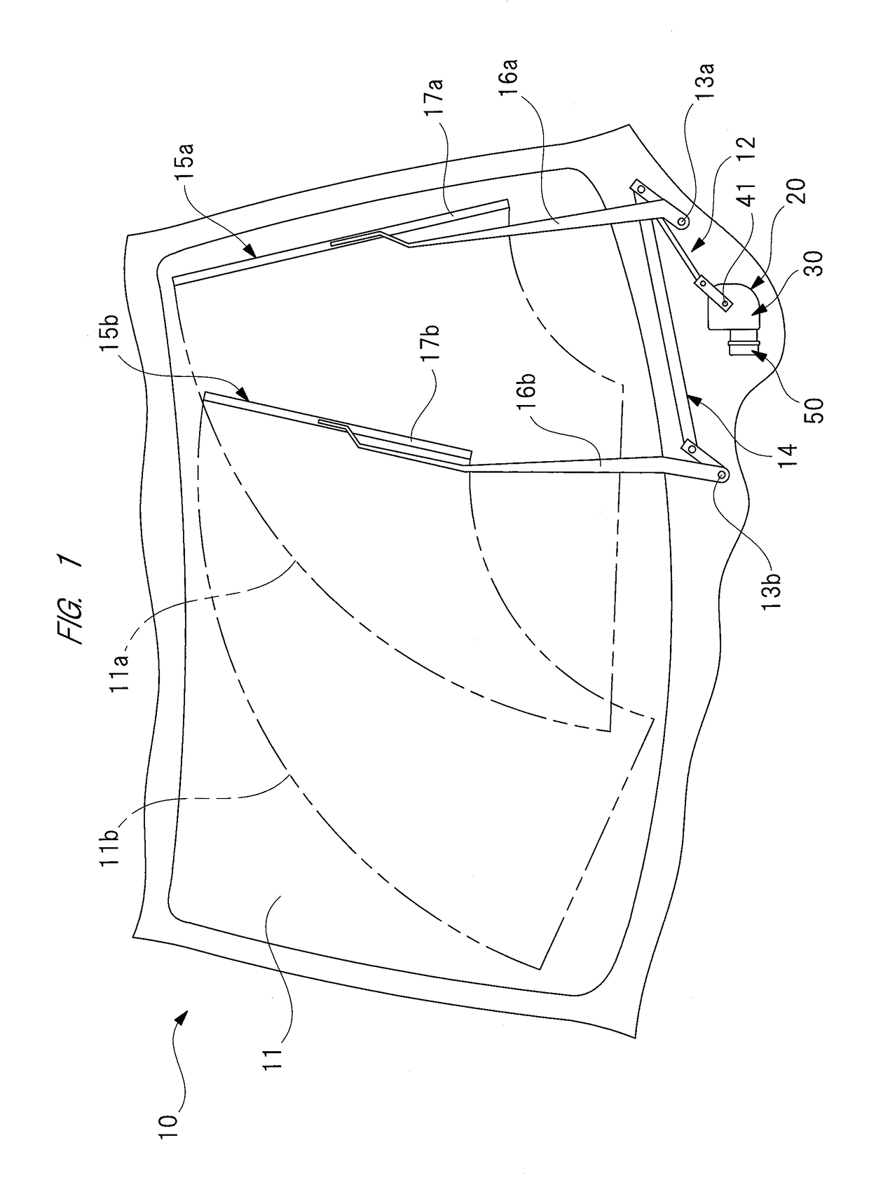
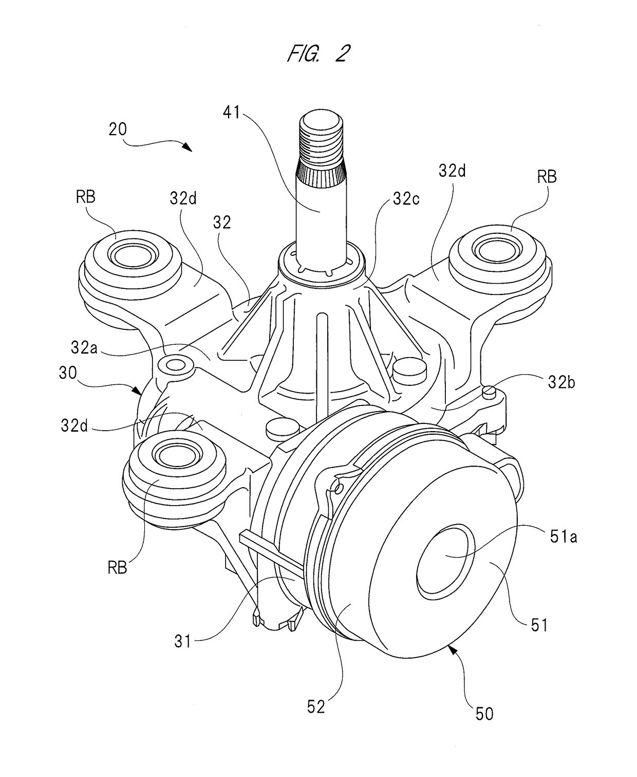
[0037]FIG. 1 is a schematic view of an in-vehicle wiper apparatus having a brushless wiper motor according to the present invention; FIG. 2 is a perspective view of the brushless wiper motor of FIG. 1, seen from on the same side as the motor unit; FIG. 3 is an enlarged sectional view of the interior of the motor unit of FIG. 2; FIG. 4 is a sectional view taken along an A-A line of FIG. 3; FIG. 5 is an explanatory view of the detailed structure of a stator core; FIG. 6 is an enlarged sectional view of a part indicated by a broken line circle “B” in FIG. 4; FIG. 7 is a graph of comparison between a variation of a press-fitting load [N] of a conventional technique and a variation of a press-fitting load [N] of the present invention; and FIG. 8 is an explanatory view of the detailed structure of a stator core of a

[0038]As shown in FIG. 1, a vehicle 10 such as automotive vehicle has a front windshield 11. A wiper apparatus 12 is disposed on the tip end portion of the front windshield 11 ...

third embodiment

[0091]FIG. 9 is an explanatory view of the fixing structure of a stator core of a third embodiment for fixing it to a motor housing unit; FIG. 10 is an explanatory view of the detailed structure of the stator core of FIG. 9; FIG. 11 is an enlarged view of a part indicated by a broken line circle “C” in FIG. 10; FIG. 12 is an enlarged view of a part indicated by a broken line circle “D” in FIG. 11; FIG. 13 is an explanatory view of the detailed structure of the motor housing unit of FIG. 9; and FIG. 14 is an enlarged perspective view of a side wall to which the stator core of the motor housing unit of FIG. 13 is press-fitted; and FIG. 15 is an enlarged sectional view of the stator core and the motor housing unit of FIG. 9 in their fixed state.

[0092]As shown in FIG. 9, a brushless wiper motor 70 of the third embodiment has a stator core 80 and a motor housing unit 90 which are different in shape from the stator core and motor housing unit of the brushless wiper motor 20 of the first e...


PUM


Abstract

In a brushless wiper motor, first and second pressing claws (43a and 43b) are formed on an outer periphery (OP) of steel sheets (34a) forming a stator core (34), and press-fitted to an inner periphery (IP) of the motor housing unit (31) so that the stator core (34) is fixed to the motor housing unit (31), base end portions of the first and second pressing claws (43a and 43b) are respectively connected to first and second walls formed on the outer periphery (OP) of the steel sheets (34a), and tip end portions of the first and second pressing claws (43a and 43b) each serves as a free end, and are directed in a circumferential direction of the stator core (34).

Description

CROSS-REFERENCE TO RELATED APPLICATIONS[0001]This application is a National Stage application of International Patent Application No. PCT / JP2015 / 080997, filed on Nov. 4, 2015, which claims priority to Japanese Patent Application No. 2014-229259, filed on Nov. 11, 2014, each of which is hereby incorporated by reference in its entirety.TECHNICAL FIELD[0002]The present invention relates to a brushless wiper motor for swinging wiper members provided on a windshield.BACKGROUND ART[0003]Conventionally, a wiper apparatus is mounted on a vehicle such as automotive vehicle, and configured to wipe off foreign objects such as rainwater and dust on a windshield. The wiper apparatus is provided with: wiper members provided on the windshield; and a wiper motor configured to swing the wiper members. By switching on a wiper switch provided in an interior of the vehicle, the wiper motor is rotated, thereby swinging the wiper members on the windshield. Since the wiper motor is installed in a small sp...

Claims


Application Information

Patent Timeline
IPC IPC(8): B60S1/08H02K1/18H02K1/14
CPCB60S1/08H02K1/146H02K1/185
Inventor KOJIMA, NAOKIKIMURA, MASAAKIISO, YUKIYOSHI
Owner MITSUBA CORP
Learn More