
Gas sensor

a technology of gas sensor and pressure sensor, which is applied in the field of gas sensor, can solve the problems of reducing productivity and/or increasing cost, and achieve the effect of further reducing the press fitting load

Active Publication Date: 2017-10-26
NGK SPARK PLUG CO LTD
View PDF0 Cites 1 Cited by
  • Summary
  • Abstract
  • Description
  • Claims
  • Application Information

AI Technical Summary

Benefits of technology

The technical effect of this patent is to provide a way to reduce the press-fitting load when a tubular body made of metal is externally fitted to a metallic shell that holds a gas sensor element. This is important because a high press-fitting load can cause damage to the sleeve or lead to a decrease in productivity and increased cost.

Problems solved by technology

Both methods lead to reduction in productivity and / or increase in cost.

Method used


Image

  • Gas sensor
  • Gas sensor
  • Gas sensor

Examples


Embodiment Construction

[0027]Hereinafter, an embodiment of the present invention will be described.

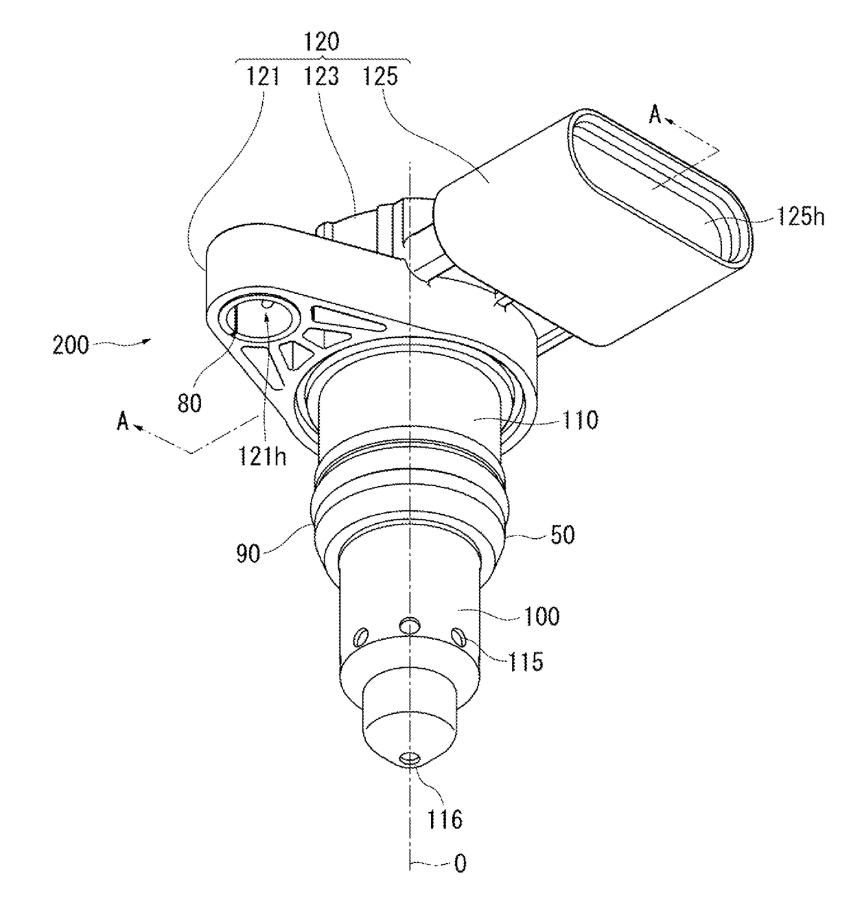
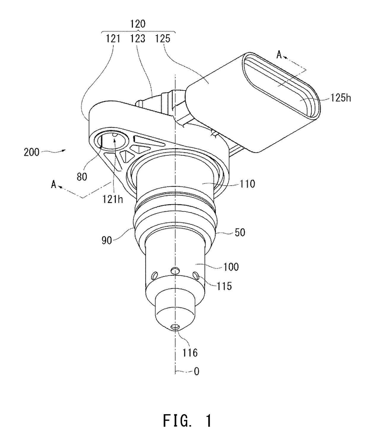
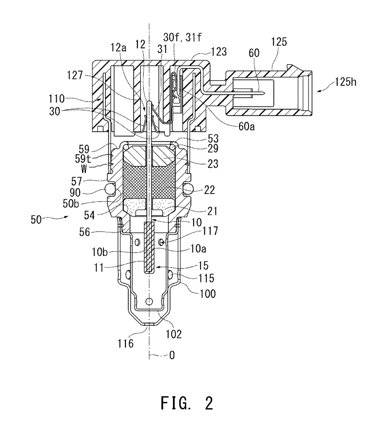
[0028]FIG. 1 is a perspective view of a gas sensor 200 according to an embodiment of the present invention. FIG. 2 is a cross-sectional view taken along a line A-A in FIG. 1. FIG. 3 shows a state in which the gas sensor 200 is mounted to a mounting target 300. The perspective view of FIG. 1 is from below (i.e., looking up toward) the gas sensor 200.

[0029]In the following description, the direction of an axis O (shown by an alternate long and short dash line) of a gas sensor element 10 is illustrated as an up-down direction, a side toward a rear end portion 12 of the gas sensor element 10 is referred to as a rear side of the gas sensor element 10 (and the gas sensor), and a side toward a detection portion 11 of the gas sensor element 10, which is opposite to the rear side (refer to FIG. 2), is referred to as a front side of the gas sensor element 10 (and the gas sensor). In addition, the direction perpendicul...


PUM

PropertyMeasurementUnit
diameteraaaaaaaaaa
outer diameteraaaaaaaaaa
concentrationaaaaaaaaaa

Abstract

A gas sensor includes: a gas sensor element 10 having a detection portion 11; a metallic shell 50 holding the gas sensor element; and a tubular body 110 made of metal, which is welded in a state of being externally fitted to a front side or a rear side of the metallic shell. The tubular body is tightly fitted to a tapered portion 59t that is provided at an outer surface of the metallic shell and is radially narrowed toward the tubular body. The tubular body is welded at the tapered portion.

Description

CROSS REFERENCE TO RELATED APPLICATION[0001]The present application claims priority to Japanese Patent Application No. 2016-085220, which was filed on Apr. 21, 2016, the disclosure of which is herein incorporated by reference in its entirety.BACKGROUND OF THE INVENTIONField of the Invention[0002]The present invention relates to a gas sensor including a gas sensor element for detecting the concentration of a gas under measurement.Description of Related Art[0003]Hitherto, a gas sensor is mounted to an intake system (e.g., an intake pipe or an intake manifold) of an internal combustion engine such as a diesel engine or a gasoline engine, and the concentration of a specific gas is monitored by the gas sensor to control the condition of combustion or the like. In this gas sensor, a gas detection element is held in a metallic shell, a front end portion of the gas detection element, which protrudes frontward relative to the metallic shell, is covered with a tubular protector made of metal,...

Claims


Application Information

Patent Timeline
Patent Type & Authority Applications(United States)
IPC IPC(8): G01N33/00
CPCG01N33/0036G01N27/409G01N33/0009
Inventor YONEZU, KUNIHIKOOBA, TAKEHIRO
Owner NGK SPARK PLUG CO LTD
Learn More