Solid polymer electrolyte fuel cell with improved voltage reversal tolerance
a solid polymer electrolyte and voltage reversal technology, applied in the direction of fuel cells, cell components, electrical equipment, etc., to achieve the effect of improving voltage reversal tolerance and durability
- Summary
- Abstract
- Description
- Claims
- Application Information
AI Technical Summary
Benefits of technology
Problems solved by technology
Method used
Image
Examples
##ventive example 1
Inventive Example 1
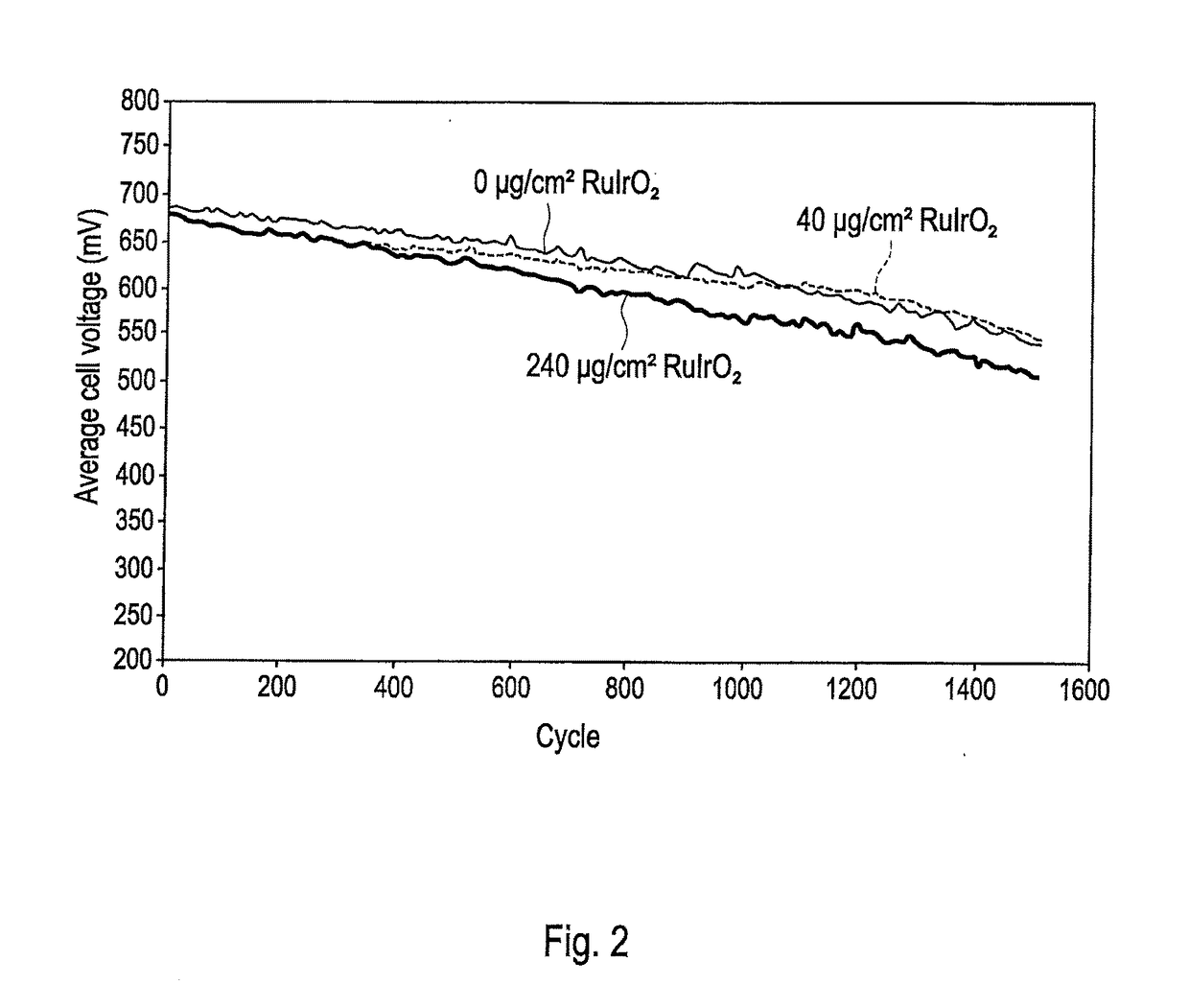
[0044]A series of cells was again made as in Comparative Example 1 above comprising RuIrO2 in the anodes. Two comparative cells were made in which the RuIrO2 was provided as an admixture in the primary anode layer as above in amounts of either 20 or 240 μg / cm2 by weight of RuIrO2. These cells were denoted Comparative 20 μg / cm2 RuIrO2 and Comparative 240 μg / cm2 RuIrO2 respectively. Note that the Comparative 20 μg / cm2 RuIrO2 cell had a cathode Pt loading of 250 μg / cm2 and anode loading of 50 μg / cm2, while the Comparative 240 μg / cm2 RuIrO2 cell had a cathode Pt loading of 400 μg / cm2 and anode loading of 100 μg / cm2. A third Comparative cell with no RuIrO2 was also prepared. Finally, a cell of the invention was prepared with no RuIrO2 in the primary anode layer and a primary anode Pt loading of 50 μg / cm2. Instead, a secondary anode catalyst composition comprising 20 μg / cm2 RuIrO2 was provided at the interface between the primary anode layer and the microporous layer of...
##ventive example 2
Inventive Example 2
[0050]A series of cells was made as in Inventive Example 1 but with varied loadings of RuIrO2 in the secondary catalyst composition layer applied to the anode GDL. Cells in this series included either 10, 20, 40, or 80 μg / cm2 of RuIrO2 in the applied layer.
[0051]Polarization tests were then performed as in the preceding on each cell after fabrication. There was no significant difference in polarization performance between cells. Thus, varying the secondary catalyst composition loading over these amounts seemed to have no impact on polarization performance.
[0052]Extended reversal tests were also performed on the cells in a similar but not identical manner to the preceding. Certain parameters differed, and particularly the relative humidities of the reactant gases employed, from those employed above. As a consequence, the absolute values for results obtained for a similar cell in the present Example differ from, and cannot properly be compared to, those in the previ...
##ventive example 3
Inventive Example 3
[0054]Another series of cells was made as in Inventive Example 1 but with varied amounts of carbon black additive added to the RuIrO2 based ink and thus also to the secondary catalyst composition layer applied to the anode GDL. Cells in this series included either 0, 10, 20 or 40 μg / cm2 of carbon additive with a constant RuIrO2 content as in Inventive Example 1 of 20 μg / cm2.
[0055]Polarization and extended reversal tests were then performed as in the preceding on each cell after fabrication. Again, there was no significant difference in polarization performance between cells. Thus, the addition of carbon additive in these amounts seemed to have no impact on polarization performance.
[0056]Table 2 compares reversal tolerance times for each of these cells. Including 10 μg / cm2 of carbon additive appeared to increase the reversal tolerance time by 7% compared to that of a cell with no carbon additive (but note that this is believed to be just within test error). However...
PUM
| Property | Measurement | Unit |
|---|---|---|
| output voltage | aaaaa | aaaaa |
| average cell voltage | aaaaa | aaaaa |
| power | aaaaa | aaaaa |
Abstract
Description
Claims
Application Information
 - R&D
- Intellectual Property
- Life Sciences
- Materials
- Tech Scout
- Unparalleled Data Quality
- Higher Quality Content
- 60% Fewer Hallucinations
Browse by: Latest US Patents, China's latest patents, Technical Efficacy Thesaurus, Application Domain, Technology Topic, Popular Technical Reports.
© 2025 PatSnap. All rights reserved.Legal|Privacy policy|Modern Slavery Act Transparency Statement|Sitemap|About US| Contact US: help@patsnap.com


