Eureka AIR delivers breakthrough ideas for toughest innovation challenges, trusted by R&D personnel around the world.

System for automated measurement of fluid output

a technology of automatic measurement and fluid output, which is applied in the direction of diagnostic recording/measuring, instruments, applications, etc., can solve the problems of affecting patient care, reducing the accuracy of measurement, and affecting the nature of urine output measurement,

Inactive Publication Date: 2017-10-26
UROSTAT LLC
View PDF9 Cites 22 Cited by
  • Summary
  • Abstract
  • Description
  • Claims
  • Application Information

AI Technical Summary

Benefits of technology

The invention is a device that can measure the output of fluids (like urine) and update a patient's electronic medical record (EMR) in real-time. It is designed to be attached to a patient's bed rail or other fixed point and collect the fluid in a container below. The device has a load cell that detects strain or stress when fluid is added, and sends a corresponding signal to a microprocessor. The microprocessor filters out noise and calculates the volume and flow rate of the fluid. The data is then sent to the EMR in real-time. The device can be connected to the EMR through a computer or a cloud storage. The technical effect of this invention is to provide healthcare providers with accurate and up-to-date information to inform their treatment decisions.

Problems solved by technology

The manual nature of urine output measurement can negatively affect patient care.
Visual inspection of the graduated cylinder introduces human error and decreases the accuracy of the measurements.
More importantly, the time between measurements can be delayed and occasionally a measurement can be missed altogether because of the many tasks a nurse is responsible for throughout the day associated with a large patient load.
Thus, any irregularities in urine output are often detected with delay, and this makes it difficult for patient care providers to prescribe treatments in real-time.
These solutions have not been widely adopted due to high costs and limited efficacy.

Method used


Image

  • System for automated measurement of fluid output
  • System for automated measurement of fluid output
  • System for automated measurement of fluid output

Examples


Embodiment Construction

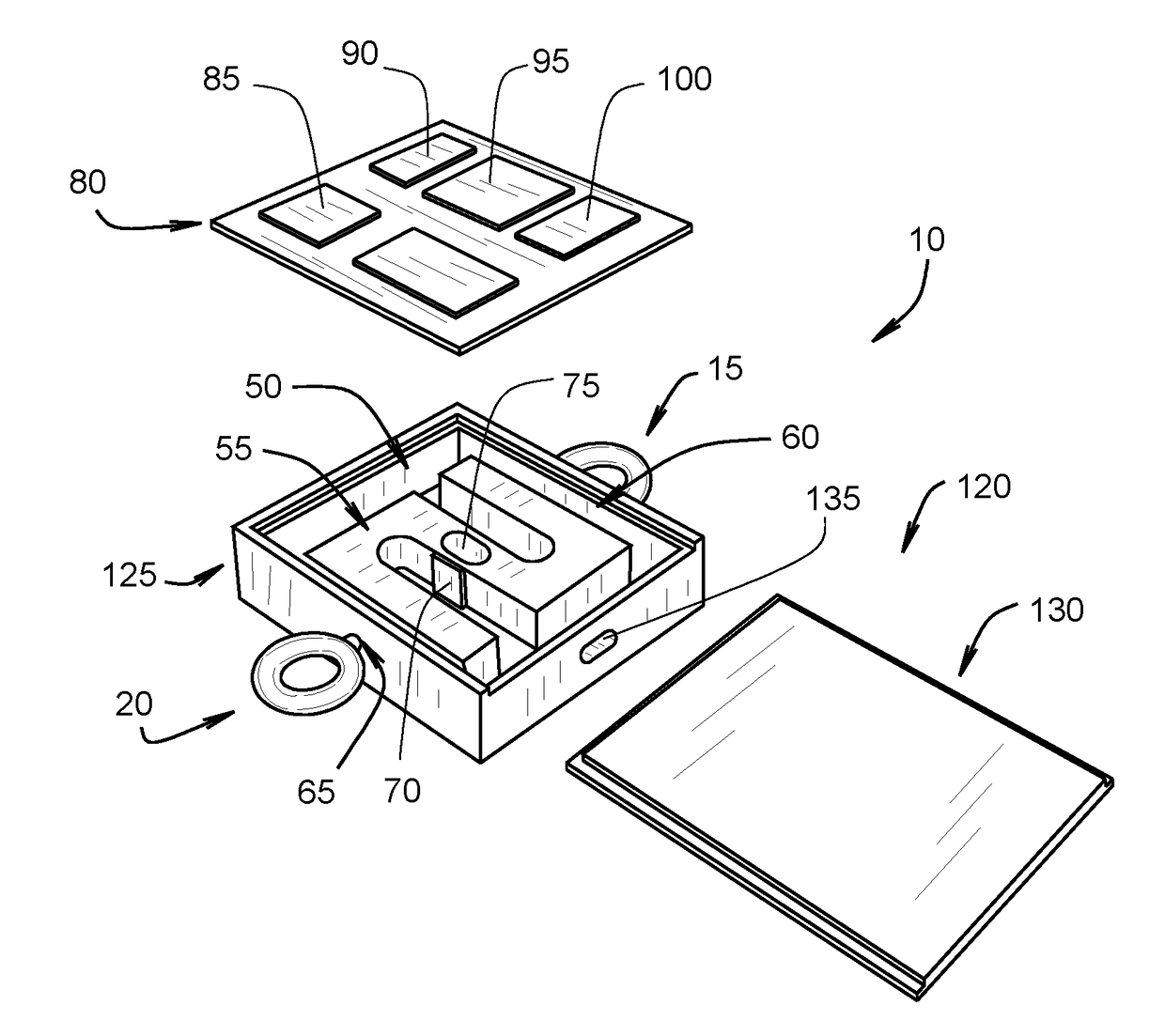
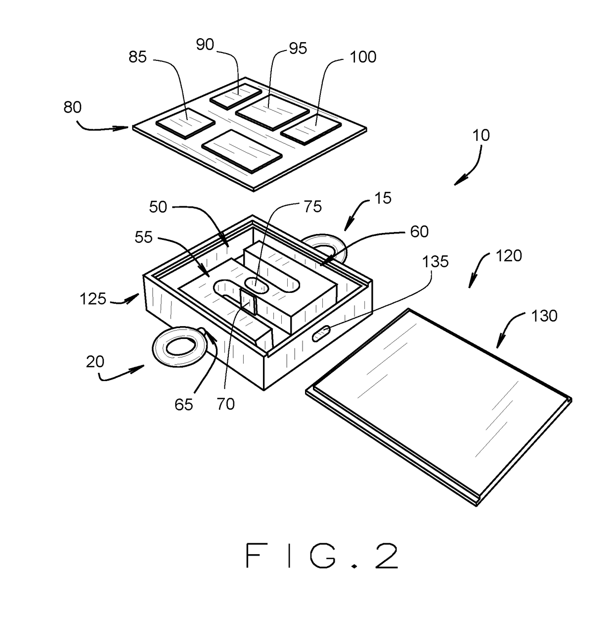
[0017]Referring to the drawings more particularly by reference numbers wherein like numbers refer to like parts, FIG. 1 illustrates a fluid output measuring device 10 constructed according to the teachings set forth below. As shown in and illustrated in FIG. 1, the fluid output measuring device 10 may include each of an upper attachment number 15 and a lower attachment member 20. The upper attachment member 15 is shown and illustrated as a circle-shaped hook including an aperture 25 at its center portion. A hook member 30 that may be attached at its upper end (not illustrated) to an existing fixed structure, such as a hospital bed railing, is preferably coupled at a lower end 35 to the upper attachment member 15. The lower attachment member 20 is preferably constructed as a hook-shaped device, as known and understood in the art.

[0018]A fluid collection container 40 is preferably in fluid communication with a patient's bladder or other fluid producing organ or body part. For example,...


PUM


Abstract

A system for automatically measuring and recording when fluid such as urine is introduced to a fluid collection container is provided. The system includes a measuring device that includes a load cell in communication with other various electronic components. The load cell is attached on one end to a fixed object like a hospital bed. At its other end, it is attached to a fluid collection container such as a urine collection bag. When fluid is introduced into the container, the load cell detects a stress change. A strain gauge (or gauges) on the load cell detects a resistance change and reads the change as a voltage change. That voltage change is amplified and digitized and converted to a weight, volume, and flow rate, before being transmitted to a recordkeeping system like electronic medical records. The system thus provides for real time measurement of fluid output collected in the container.

Description

CROSS-REFERENCE TO RELATED APPLICATIONS[0001]This application claims the benefit of U.S. Provisional Application No. 62 / 326,264, filed Apr. 22, 2016, which is hereby incorporated by reference in its entirety.BACKGROUND OF THE INVENTION[0002]The present invention relates generally to an automated method for measuring fluid output. More particularly, the invention relates to measuring the fluid (for example urine) output using a load cell.[0003]Urine output can be an important metric that guides clinical care for patients that are hospitalized and have a catheter placed in their bladders. Typically, for these patients, urine drains from the catheter through a tube and collects in a container. A nurse or other medical technician then measures the volume of urine produced approximately once an hour. These measurements often indicate to a health care professional the patient's current condition and guide a health care professional to make determinations about what should be done next. Th...

Claims


Application Information

Patent Timeline
IPC IPC(8): G01F1/05G01G3/14
CPCG01G3/1404G01F1/05A61B5/208A61F5/453G01F1/007G01F23/20G01G17/04G01G19/18
Inventor PAHWA, MRINALSUN, RAPHAEL CHUNPING
Owner UROSTAT LLC
Why Eureka
Eureka Blog
Learn More