
Telescopic shaft

a telescopic shaft and shaft technology, applied in the field of telescopic shafts, can solve the problems of preventing product inclusion and sharing, requiring a separate structure or device, and limited vehicle layou

Inactive Publication Date: 2017-10-26
KOREA FLANGE
View PDF7 Cites 5 Cited by
  • Summary
  • Abstract
  • Description
  • Claims
  • Application Information

AI Technical Summary

Benefits of technology

The present invention is a telescopic shaft that reduces play and prevents the balls from separating. It achieves this by ensuring that one ball is positioned at the intersection between two incline grooves, which prevents any play in the circumferential direction between them. This technology improves the stability and reliability of the shaft.

Problems solved by technology

In this regard, there is a problem in that vehicle layout is limited due to an angle limit of the inboard joint and a vehicle vibrates due to influence of axial force generated in the inboard joint during a period with a high angle and driving force.
In addition, even if the same joint is used in vehicles, shafts have different lengths due to different layouts between vehicles and, thus, these problems impede product inclusion and sharing due to different types of drive shafts.
However, some play occurs due to the characteristics of this structure and, thus, a problem arises in that there is a need for a separate structure or device for preventing separation of balls.

Method used


Image

  • Telescopic shaft
  • Telescopic shaft
  • Telescopic shaft

Examples


Embodiment Construction

[0024]Certain exemplary embodiments of the present invention will now be described in greater detail with reference to the accompanying drawings. As the invention allows for various changes and numerous embodiments, particular embodiments will be illustrated in the drawings and described in detail in the written description. However, this is not intended to limit the present invention to particular modes of practice, and it is to be appreciated that all changes, equivalents, and substitutes that do not depart from the spirit and technical scope of the present invention are encompassed in the present invention.

[0025]In the following description, the same reference numerals are used for the same elements even in different drawings.

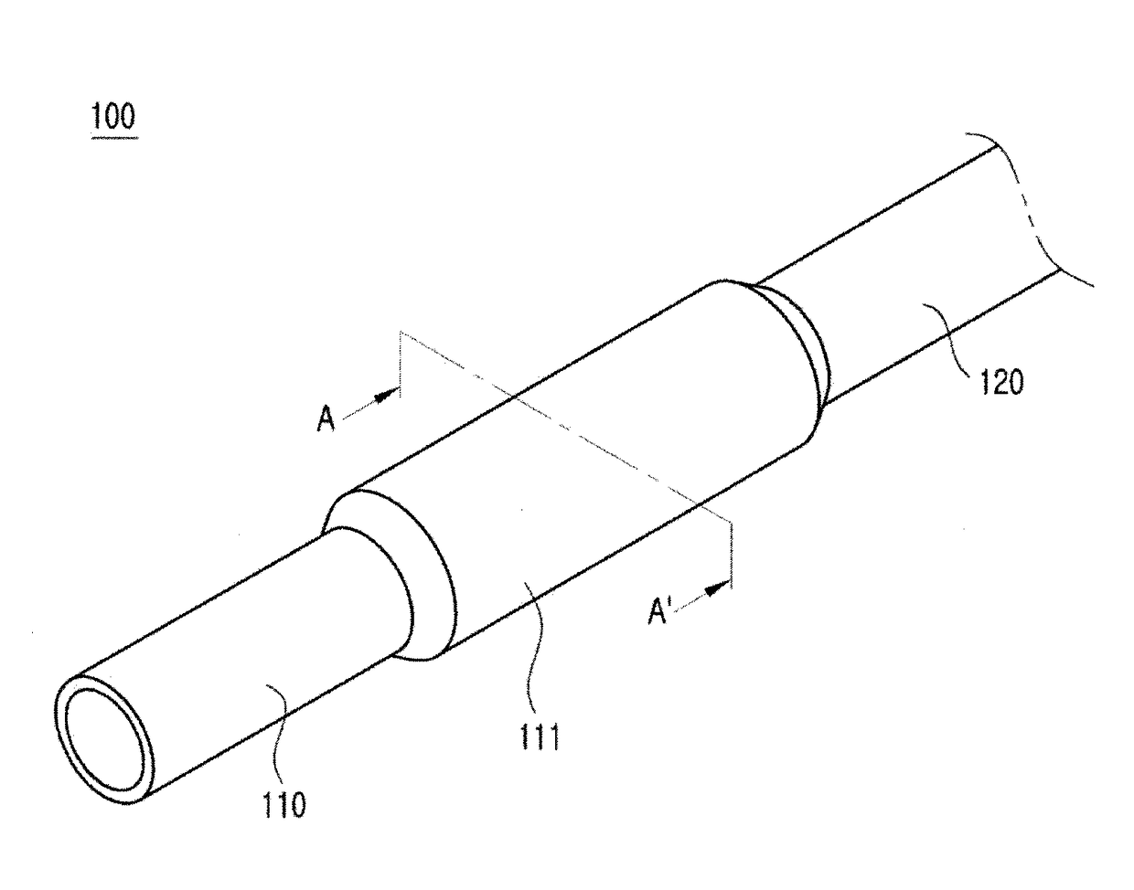
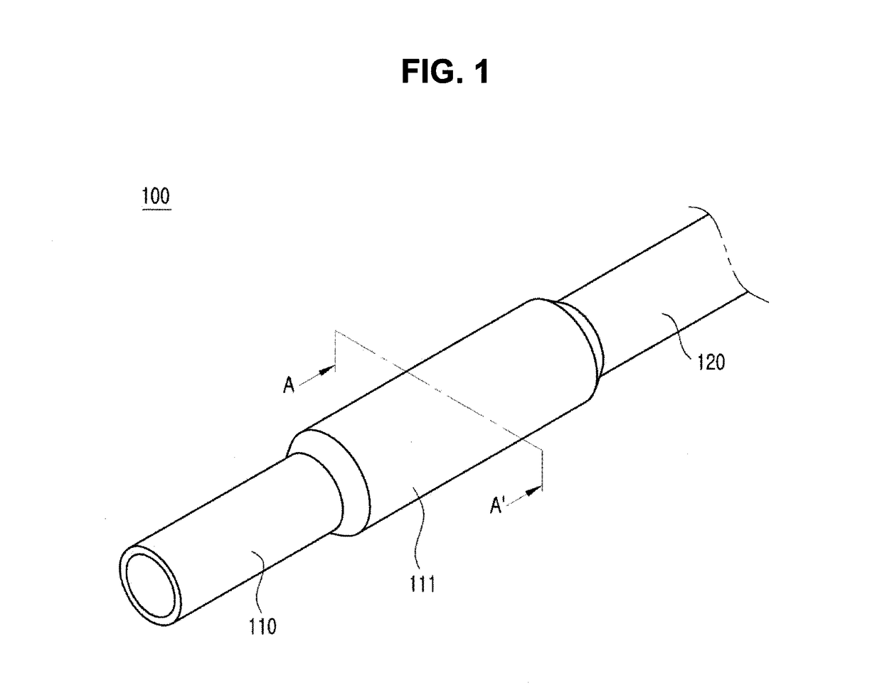
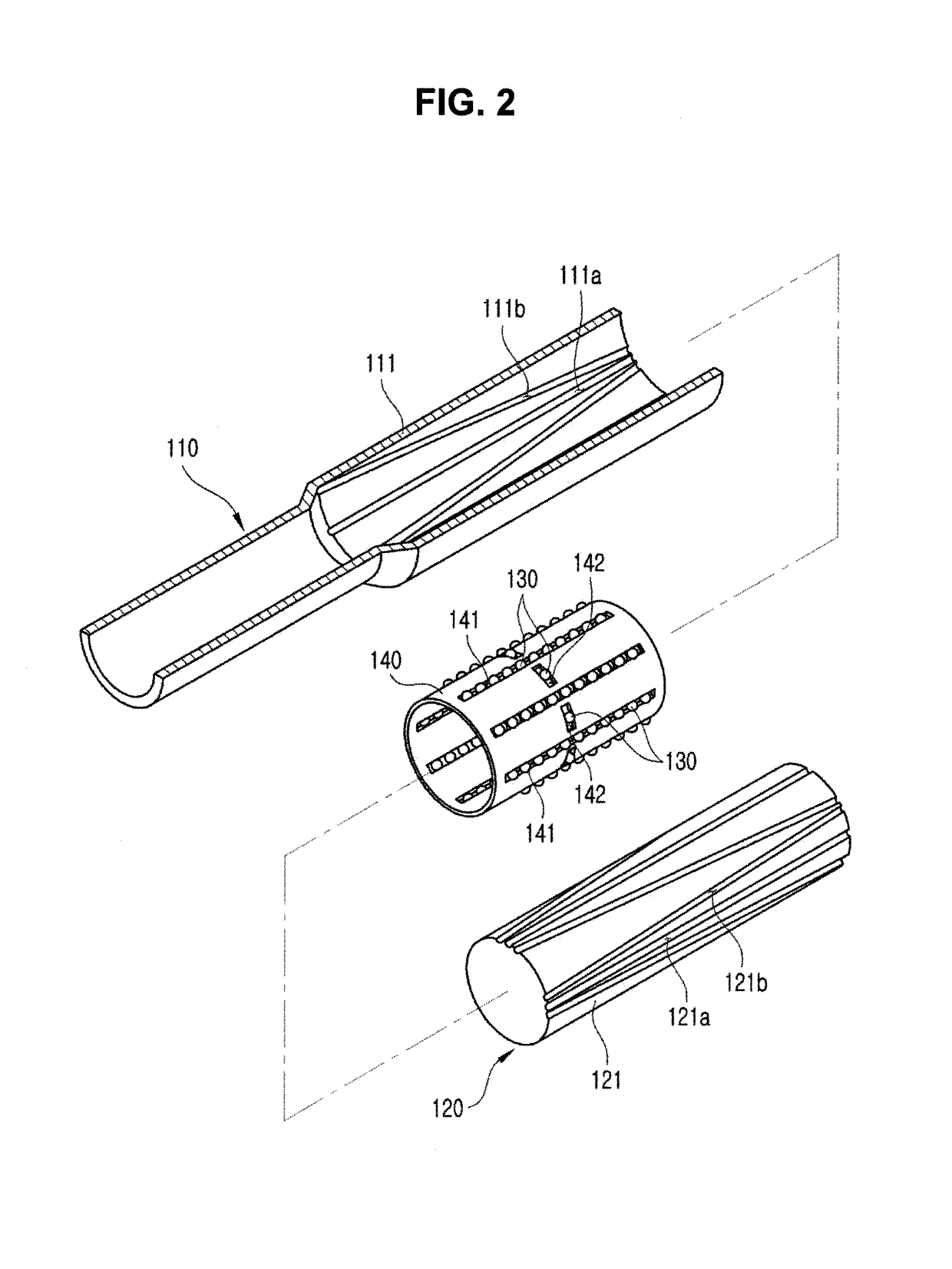
[0026]FIG. 1 is a perspective view of a telescopic shaft 100 according to an exemplary embodiment of the present invention. FIG. 2 is a partially exploded perspective view of the telescopic shaft 100 according to an exemplary embodiment of the present invent...


PUM


Abstract

A telescopic shaft is provided. The telescopic shaft includes a first shaft including a first coupler having an inner circumferential surface including an external straight groove and an external inclination groove formed thereon, the external straight groove having a semi-circular cross section and being formed in parallel to a rotation axis and the external inclination groove having a semi-circular cross section, being inclined with respect to the external straight groove at a predetermined angle, and being shaped like a spiral, a second shaft including a second coupler inserted into the first coupler and having an outer circumferential surface including an internal straight groove and an internal inclination groove formed thereon, the internal straight groove having a semi-circular cross section and corresponding to the external straight groove and the internal inclination groove having a semi-circular cross section, being inclined in an opposite direction to the external inclination groove at a predetermined angle with respect to the internal straight groove, and being shaped like a spiral, and a plurality of balls arranged in a line in an axial direction between the external straight groove and the internal straight groove, one ball being arranged between the external inclination groove and the internal inclination groove, wherein the first shaft and the second shaft are coupled to extend and retract in an axial direction, thereby preventing play from occurring in a circumferential direction and preventing separation of balls.

Description

CROSS-REFERENCE TO RELATED APPLICATIONS[0001]This application claims priority from Korean Patent Application No. 10-2016-0050458 filed on Apr. 25, 2016, in the Korean Intellectual Property Office, the disclosure of which is incorporated herein by reference in its entirety.BACKGROUND OF THE INVENTIONField of the Invention[0002]Apparatuses and methods consistent with the present invention relate to a telescopic shaft, and more particularly, to a telescopic shaft for minimizing play.Description of the Related Art[0003]In general, a steering wheel used a vehicle is connected to a steering gear box via a steering shaft. In this case, the steering shaft rotates a gear in the steering gear box to rotate a direction of a vehicle wheel by as much as a rotation amount of the steering wheel by a driver.[0004]In general, a length of the steering shaft is basically determined according to vehicle type but, recently, a telescopic steering shaft that is adjustable in angle and length in considerat...

Claims


Application Information

Patent Timeline
Patent Type & Authority Applications(United States)
IPC IPC(8): B62D1/185F16D3/22F16D3/18F16D3/221B62D1/18
CPCB62D1/185B62D1/18F16D3/22F16D3/221F16D3/18F16C3/035F16C29/04F16C29/12F16C2326/06F16D3/065
Inventor PARK, JEONG LYUL
Owner KOREA FLANGE
Learn More