Terminal assembly for bipolar electrochemical cell or battery

a technology of bipolar electrochemical cells and terminal assemblies, which is applied in the direction of cell components, final product manufacturing, sustainable manufacturing/processing, etc., can solve the problems of reducing battery capacity and cycle life, negatively affecting battery performance as electrical energy storage devices, and severely limited battery performance of traditional zinc-halide batteries. achieve uniform zinc plating, enhance battery performance, and promote battery performan

Active Publication Date: 2017-10-19
EOS ENERGY TECH HLDG LLC
View PDF0 Cites 1 Cited by
  • Summary
  • Abstract
  • Description
  • Claims
  • Application Information

AI Technical Summary

Benefits of technology

[0007]The present invention provides a terminal assembly for a zinc-halide (e.g., zinc-bromide) electrochemical cell that promotes enhanced battery performance (e.g., battery cycle life, battery capacity, and substantial uniformity in discharge current) through substantially uniform zinc plating on a bipolar electrode plate and enhances battery performance (e.g., cycle life, capacity, or the like).
[0027]Another aspect of the present invention provides a battery stack defining a longitudinal axis, the battery stack comprising a pair of terminal assemblies at corresponding proximal and distal ends of the electrochemical cell assembly, each terminal assembly comprising a conductive cup-shaped member comprising a terminal wall, a sidewall, and a rim separated from the terminal wall by the sidewall; and a terminal endplate having inner and outer surfaces coplanar with the terminal wall and joining to the corresponding rim at the outer surface, the joining enabling bi-directional uniform current flow through the cup-shaped member between a corresponding terminal and the terminal endplate when the corresponding terminal wall is in contact with the corresponding terminal; at least one pair of bipolar electrodes arranged in parallel along the longitudinal axis and interposed between the pair of terminal assemblies, each pair of bipolar electrodes comprising a first bipolar electrode of at least one pair of bipolar electrodes, the first bipolar electrode comprising a first bipolar electrode plate; a first carbon material; a first separator; and a first cathode cage configured to hold the first carbon material in electrical communication with a first front surface of the first bipolar electrode plate; and a second bipolar electrode of the at least one pair of bipolar electrodes, the second bipolar electrode comprising a second bipolar electrode plate; a second carbon material; a second separator; and a second cathode cage configured to hold the second carbon material in electrical communication with a second front surface of the second bipolar electrode plate; and an aqueous electrolyte interposed between the first bipolar electrode plate and the second electrode plate.

Problems solved by technology

However, battery performance of traditional zinc-halide batteries is severely limited due to uneven zinc plating on the bipolar electrode during charging.
Uneven or irregular zinc plating on the bipolar electrode generates zinc dendrites in the battery and reduces battery capacity and cycle life.
Moreover, uneven zinc plating creates heterogeneity in battery discharge currents that negatively affects battery performance as a storage device for electrical energy.

Method used


Image

  • Terminal assembly for bipolar electrochemical cell or battery
  • Terminal assembly for bipolar electrochemical cell or battery
  • Terminal assembly for bipolar electrochemical cell or battery

Examples


example 1a

e Formulations

[0332]Ingredients used in the electrolyte formulations described below were reagent grade.

TABLE 1Ingredients for electrolyte ingredientsIngredientSourceZnBr2 (73-79% ZnBr2 soln. in water)ICL IP America, Inc., Carteret, NJKBrAlfa Aesar, Ward Hill, MAKClAlfa Aesar, Ward Hill, MAtetraglymeSigma Aldrich Corp., St. Louis, MODME-PEG 2000Sigma Aldrich Corp., St. Louis, MODME-PEG 1000Alfa Aesar, Ward Hill, MAN-methyl-n-ethylmorpholinium bromideICL-IP Bromine Compounds, Ltd.,Beer-Sheva, Israelneopentyl glycolSigma Aldrich Corp., St. Louis, MOtert-butyl alcoholAlfa Aesar, Ward Hill, MASn (SnCl2•2H2O)Alfa Aesar, Ward Hill, MAIn (5% v / v in dilute nitric acid - 10,050 μg / ml)Inorganic Ventures, Christiansburg, VAacetic acid (glacial)Alfa Aesar, Ward Hill, MA18-crown-6 etherSigma Aldrich Corp., St. Louis, MO15-crown-5 etherSigma Aldrich Corp., St. Louis, MOtetraethylammonium bromideAlfa Aesar, Ward Hill, MA1-ethyl-2-methylpyridinium bromideICL-IP Bromine Compounds, Ltd.,Beer-Sheva, I...

example 1b

mical Cells Including Electrolyte Formulations of Example 1A

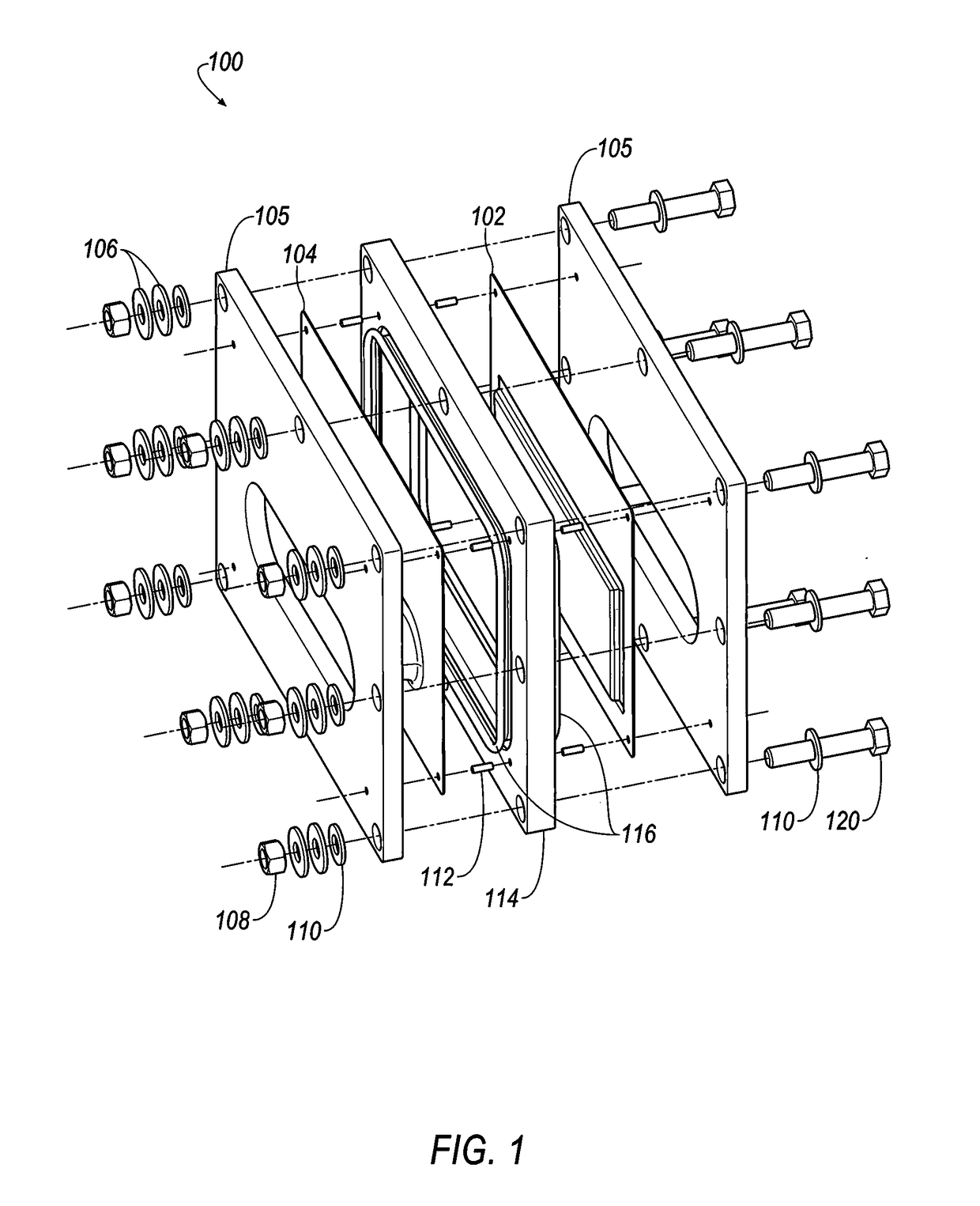
[0347]Referring to FIGS. 35-38, selected electrolytes, formulated as described in Example 1A, above, were added to dry electrochemical test cells that were evaluated for discharge capacity, Coulombic efficiency, Run Time, and energy efficiency as a function of charge cycle no. The dry cells used in this example were formed as illustrated in FIG. 1. Each of the test cells included a Calgon Carbon Zorflex ACC FM-10 carbon cloth separator that was cut into rectangles (width˜5.31 cm, length˜12.076 cm) using a steel ruled die coated in ZrN of the same shape. The carbon material was formulated with 20 kg of PTFE dispersion (60 wt %) (DuPont DISP30 PTFE dispersion), 10 kg Cabot PBX52 carbon blacks, 1 kg carbon fibers (3 mm), 10 kg Akzo-Nobel Ketjenblack EC600JD carbon blacks and 10 kg of de-ionized water. The dry ingredients were premixed in a 55 gallon drum with an anti-static drum liner to form a relatively homogeneous mixture t...

example 2

te No. 2-1

[0349]Bipolar Static (Non-Flowing) Cell Testing:

[0350]The following electrolyte formulations were tested in battery stacks, illustrated in FIGS. 18-20.

[0351]Each of the 28 bipolar electrodes of the battery stacks included a Calgon Carbon Zorflex ACC FM-10 carbon cloth separator that was cut into rectangles (width˜5.31 cm, length˜12.076 cm) using a steel ruled die coated in ZrN of the same shape. The carbon material was formulated with 20 kg of PTFE dispersion (60 wt %) (DuPont DISP30 PTFE dispersion), 10 kg Cabot PBX52 carbon blacks, 1 kg carbon fibers (3 mm), 10 kg Akzo-Nobel Ketjenblack EC600JD carbon blacks and 10 kg of de-ionized water. The dry ingredients were premixed in a 55 gallon drum with an anti-static drum liner to form a relatively homogeneous mixture to which the PTFE dispersion and de-ionized water were added, and the resulting mixture was stirred to generate a dough material. The dough material was formed from into blocks (length˜5.24 cm, width˜3.94 cm, thi...


PUM

PropertyMeasurementUnit
surface areaaaaaaaaaaa
surface areasaaaaaaaaaa
radiusaaaaaaaaaa

Abstract

The present invention provides a terminal assembly, and storage batteries comprising a terminal assembly, wherein the terminal assembly comprises a conductive cup-shaped member comprising a terminal wall in electric communication with a terminal of the electrochemical cell when the terminal wall is in contact with the terminal; a sidewall; and a rim separated from the terminal wall by the sidewall; and a bipolar endplate having first and second surfaces coplanar with the terminal wall and joining to the rim at the first surface, the joining enabling bi-directional uniform current flow through the cup-shaped member between the terminal and the endplate when the terminal wall is in contact with the terminal, the endplate having an electrochemically active region comprising a first surface area enclosed by the rim and a remaining second surface area outside an outer periphery of the rim, the first and second surface areas being substantially equal.

Description

CROSS REFERENCE TO RELATED APPLICATION[0001]This PCT application claims the benefit of U.S. provisional application No. 62 / 060,273, filed on Oct. 6, 2014; 62 / 170,200, filed on Jun. 3, 2015; and 62 / 173,415, filed on Jun. 10, 2015. Each of these documents is incorporated herein by reference in its entirety.TECHNICAL FIELD[0002]This invention relates to an assembly for rechargeable bipolar electrochemical cells or rechargeable bipolar battery stacks. More specifically, this invention relates to a terminal assembly for rechargeable bipolar electrochemical cells or rechargeable bipolar battery stacks (e.g., zinc-halide batteries) that generates a substantially uniform current flow to and from the storage battery during battery charging and discharging.BACKGROUND[0003]Zinc-halide batteries were developed as devices for storing electrical energy. Traditional zinc-halide batteries (e.g., zinc-bromine batteries) employed bipolar electrodes disposed in a static, i.e., non-flowing, zinc-bromid...

Claims


Application Information

Patent Timeline
Patent Type & Authority Applications(United States)
IPC IPC(8): H01M2/30H01M10/04H01M4/04H01M10/056H01M10/36H01M4/02H01M50/553H01M50/562
CPCH01M2/30H01M10/365H01M10/0463H01M2004/029H01M10/056H01M4/0473H01M2300/0002H01M10/0418H01M4/364H01M4/583H01M4/60H01M4/661H01M4/663H01M4/667H01M4/76H01M8/184H01M10/38H01M12/085Y02E60/10H01M50/44H01M50/46H01M50/553H01M50/562Y02P70/50Y02E60/50H01M10/044H01M50/543H01M50/431
Inventor ADAMSON, GEORGE W.BOWERS, SARA S.
Owner EOS ENERGY TECH HLDG LLC
Why Eureka
Try Eureka