
Methods for improvements of the box wing aircraft concept and corresponding aircraft configuration

Active Publication Date: 2017-10-19
HERNADI ANDRAS
View PDF1 Cites 6 Cited by
  • Summary
  • Abstract
  • Description
  • Claims
  • Application Information

AI Technical Summary

Benefits of technology

The present invention is a new type of box wing aircraft that has several improved qualities. It is flexible with cargo placement, has good maneuverability and stability, and provides more safety with redundant aerodynamic devices. Additionally, it reduces noise and engine power at takeoff and landing, and allows for the use of stronger composite materials in the wings. These features make it easier to build large, extended aircraft with manageable wingspan.

Problems solved by technology

It is desirable for airliners to carry more than a thousand passengers, but such a monoplane is difficult to design, because of the large wingspan.
Such a large aircraft is not easy to design as a box wing biplane either.
It may prove that the closed frame structure of the front and rear wings is not sufficiently strong and stiff.
There is a risk that the wingtip fence of the regular, conventional biplane box wing configuration must be strengthened a lot and might therefore be too heavy.
But airliners must carry a lot of fuel in the huge wings for long distance flights.
It is necessary to obtain sufficient horizontal and vertical separation between multiple wings because of the aerodynamic interference issue.
The four engines of the aircraft in question form no part of the claimed design but this aircraft is not functional because all the four engines are clearly Ramjet-type engines which need an established airflow of several hundred km / h for start.
Furthermore, airport boarding bridges are not designed for a box wing aircraft.

Method used


Image

  • Methods for improvements of the box wing aircraft concept and corresponding aircraft configuration
  • Methods for improvements of the box wing aircraft concept and corresponding aircraft configuration
  • Methods for improvements of the box wing aircraft concept and corresponding aircraft configuration

Examples


Embodiment Construction

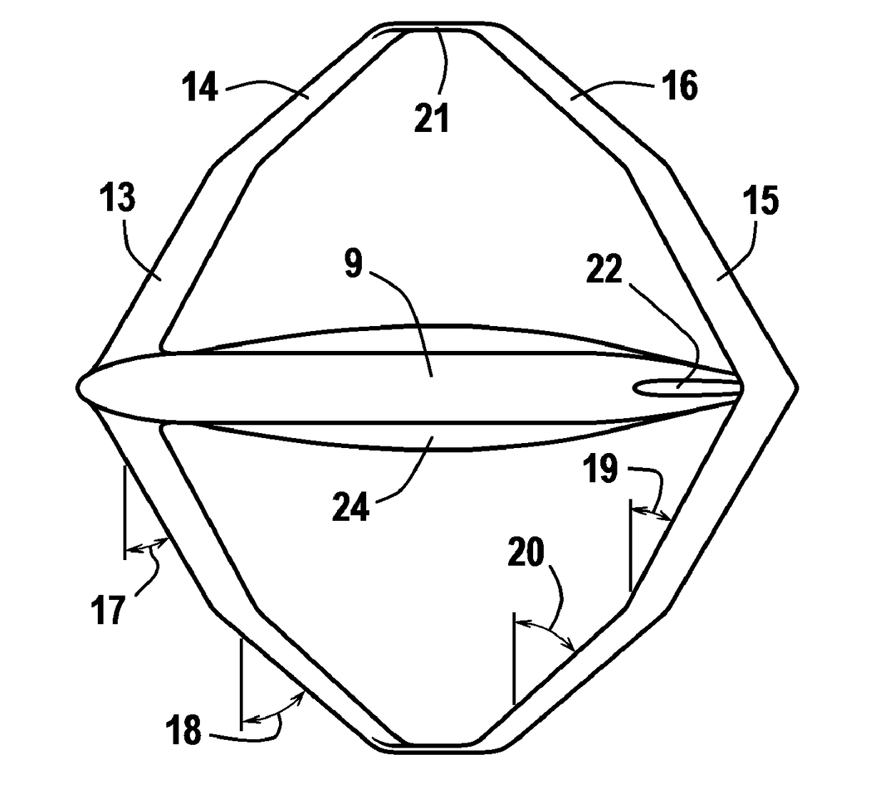
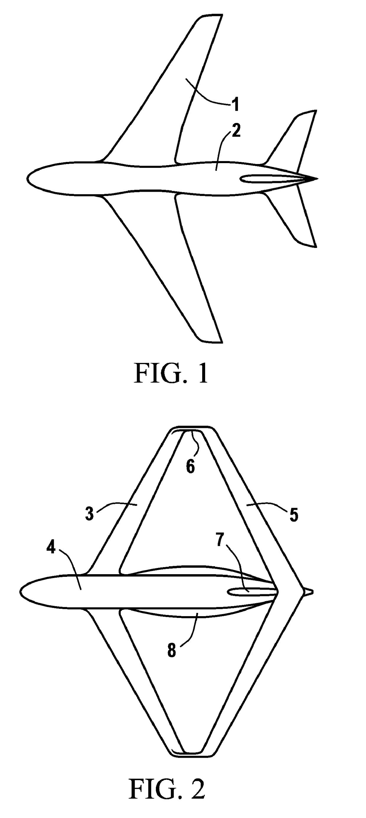
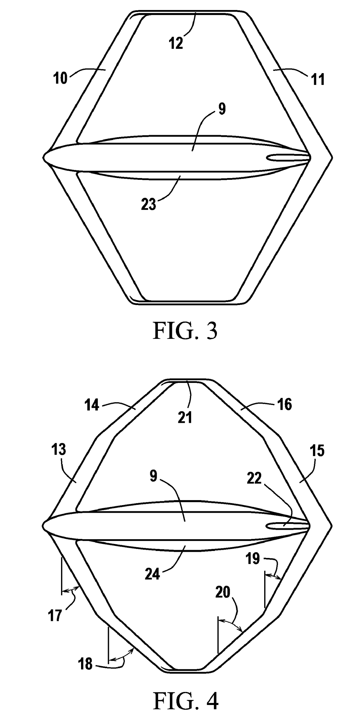
[0036]Referring now to the drawings, most of the embodiments show a large airliner or cargo plane. The present invention is in no way limited to this type of aircraft; it is applicable to any aircraft of any size, any purpose and application; manned or unmanned; and with any type of propulsion or combination of different propulsion systems for different flying conditions, without any limit as regards speed, altitude or function. The scope of the invention is not limited by materials. Any materials can be used allowing the construction and operation of the invention. Airfoils and other details of the embodiment and structure are established in a way that will be understood by those skilled in the art. Throughout the drawings, the symmetric aircraft parts, one positioned on one side of the fuselage and another on the opposite side, are provided with only one particular reference numeral when it is clear that the numbered item has an identical mirrored counterpart.

[0037]FIG. 1 is a top...


PUM


Abstract

Aircraft configuration by applying the following method steps for improving the conventional box wing aircraft concept: dividing both the backward swept front and the forward swept rear wings into root and tip sections, wherein the tip sections (34) of the front wings are more backward swept than the root sections (37), and the tip sections (35) of the rear wings are more forward swept than the root sections (38). Preferred embodiments comprise moving the front wing to the nose and the rear wing towards the rear end of a long fuselage; adding a middle wing and thereby decreasing the wingspan by one third; dividing the middle wing into a backward swept root section (28) and two tip sections (29,30), one forward and another backward swept. The four wingtips on each side are interconnected by a wingtip fence (26), obtaining seven closed frame structures, as well as seven aerodynamic channels for the stream flow.

Description

CROSS REFERENCE TO RELATED APPLICATIONS[0001]This application claims priority from RCD EM 002544510-0001 and 002544510-0002, both filed on Sep. 25, 2014, with OHIM / OAMI Reference “StratosLiner”; and also priority from US Design Patent Application No. 29520505 filed on Mar. 16, 2015, titled “Backward and forward swept aircraft wing sections in a decagonal box wing configuration”.BACKGROUND OF THE INVENTION[0002]This invention relates to the field of box wing aircraft design, with a focus on novel improvements of some of the features and adding new elements to the prior art in this field.[0003]The regular, conventional box wing configuration is comprised of a thin and straight backward swept and slightly dihedral front wing, a similarly thin and straight forward swept rear wing and a connecting non-lifting wingtip fence between the wingtips. The front wing root joins the lower part of the fuselage and the root of the rear wing joins the upper part of the fuselage, or the roots of the ...

Claims


Application Information

Patent Timeline
IPC IPC(8): B64C39/06B64C5/02B64C3/16
CPCB64C39/068B64C5/02B64C3/16
Inventor HERNADI, ANDRAS
Owner HERNADI ANDRAS
Learn More