Eureka AIR delivers breakthrough ideas for toughest innovation challenges, trusted by R&D personnel around the world.

Device for producing carbon nanotube fibers and method for producing carbon nanotube fibers using same

a carbon nanotube fiber and carbon nanotube technology, which is applied in the direction of aligned nanotubes, artificial filament chemical after-treatment, chemistry apparatus and processes, etc., can solve the problems of insufficient carbon nanotube characteristics, low spinning speed, and difficult dispersion of carbon nanotubes at a high concentration, so as to facilitate the discharge of carbon nanotube fiber and facilitate continuous long-term operation of the apparatus , the effect of reducing the contamination of the inner wall of the reactor

Active Publication Date: 2017-10-12
LG CHEM LTD
View PDF5 Cites 14 Cited by
  • Summary
  • Abstract
  • Description
  • Claims
  • Application Information

AI Technical Summary

Benefits of technology

The present invention provides an apparatus for efficient production of carbon nanotube fibers. Gas curtains are formed to prevent contamination of the reactor inner wall and facilitate the discharge of the carbon nanotube fibers. This reduces the risk of damage to the fibers during production. The carbon nanotube fibers have a variety of applications, including reinforcing agents of multifunctional composite materials and electrochemical devices. The technical effects of the invention are improved efficiency in producing high-quality carbon nanotube fibers.

Problems solved by technology

However, high cohesive strength of carbon nanotubes due to their strong van der Waals force makes it not easy to disperse the carbon nanotubes at a high concentration while maintaining their dispersibility.
Further, in composite materials using carbon nanotubes as reinforcing agents, the excellent characteristics of the carbon nanotubes are not sufficiently exhibited.
This method is advantageous in that well-aligned carbon nanotube fibers can be produced, but has the disadvantages of very low spinning speed and strict conditions for the formation of liquid crystals of carbon nanotubes.
For these reasons, it is very difficult to easily discharge the carbon nanotube fiber particles.
However, since the catalyst is formed after colliding with the inner wall of the reactor, its flow becomes very irregular in and near the region where the catalyst is formed, and as a result, its size distribution becomes broad, which makes it difficult to produce carbon fibers with a sharp size distribution.
Further, since the catalyst used in the initial synthesis of carbon fibers is allowed to react with a raw material by spraying the catalyst towards the inner wall of a reactor, it is difficult to produce branched carbon fibers with a uniform outer diameter.

Method used

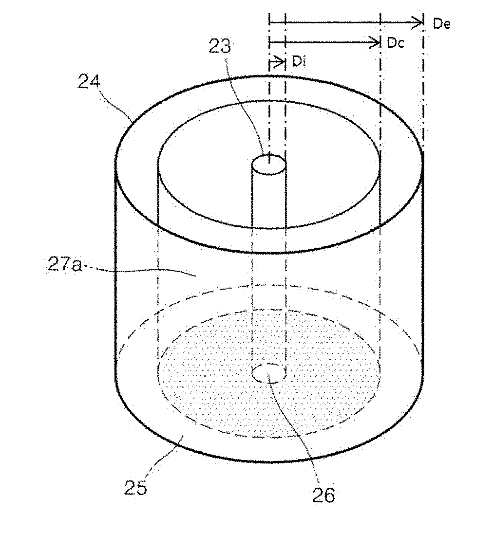
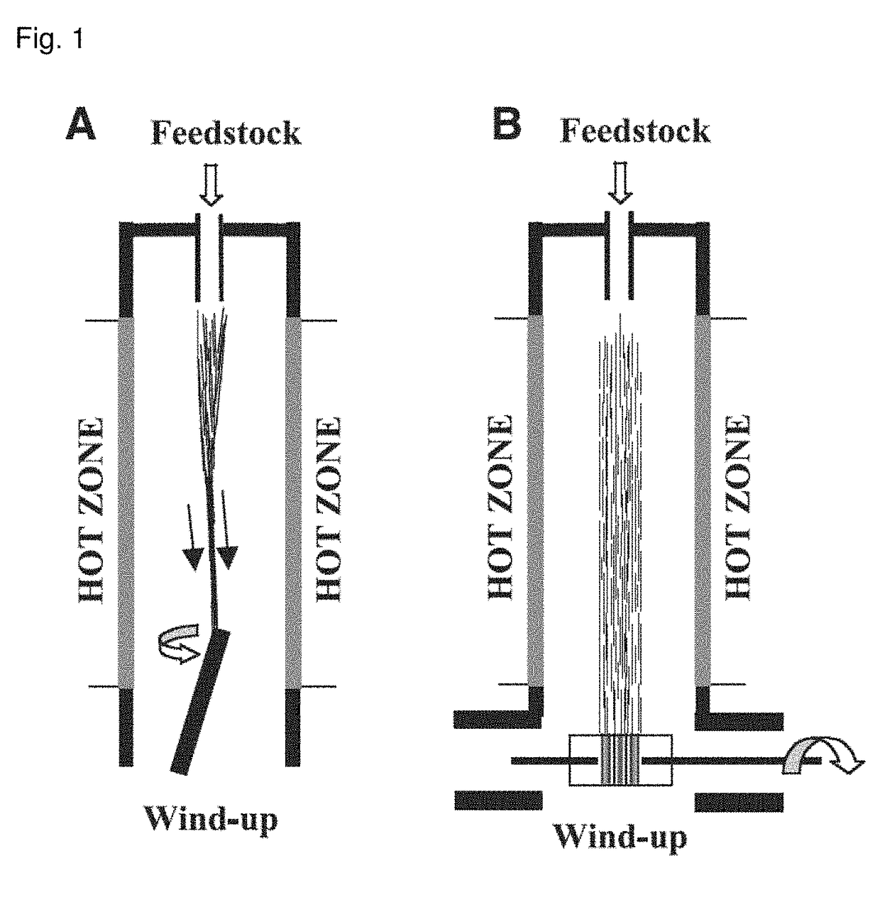
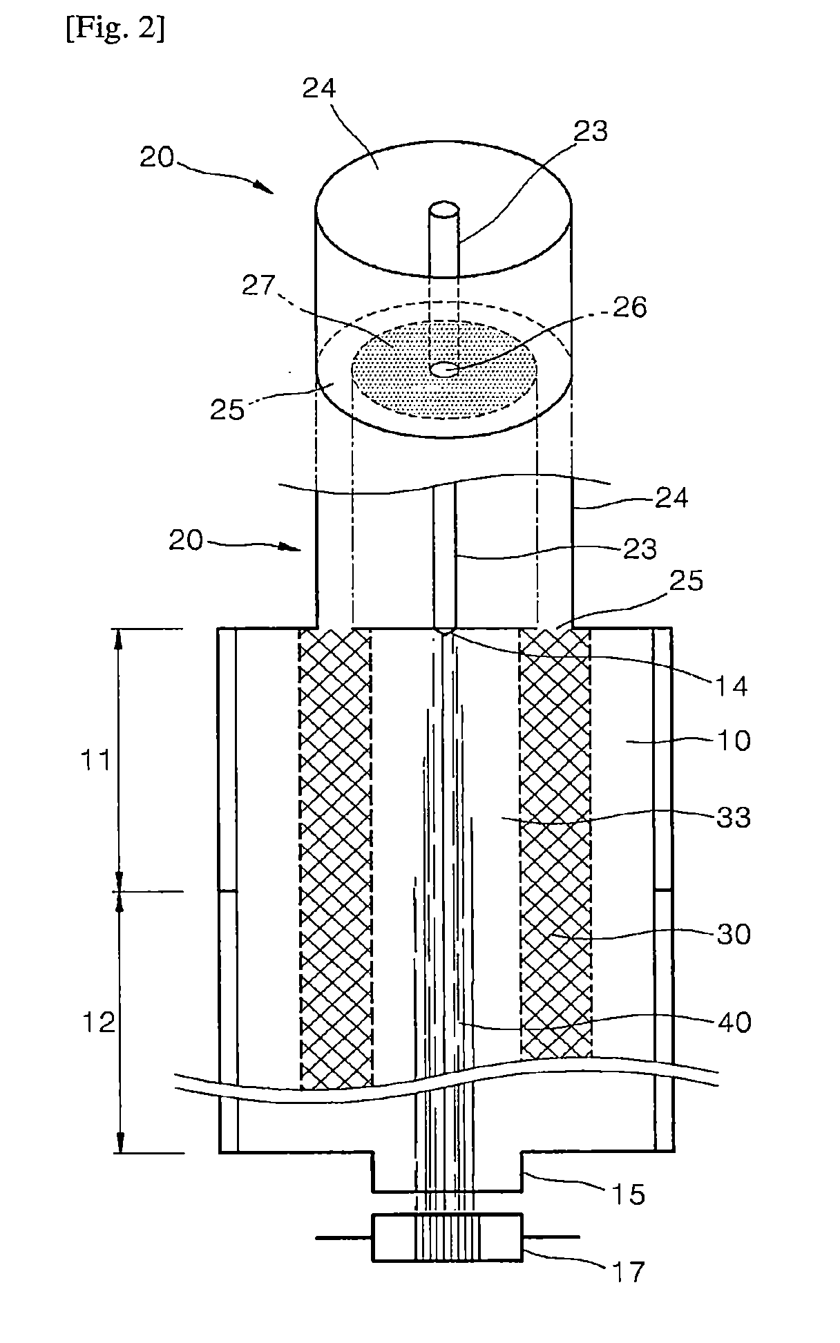

Image

  • Device for producing carbon nanotube fibers and method for producing carbon nanotube fibers using same
  • Device for producing carbon nanotube fibers and method for producing carbon nanotube fibers using same
  • Device for producing carbon nanotube fibers and method for producing carbon nanotube fibers using same

Examples


Embodiment Construction

[0040]The present invention will now be described in more detail with reference to embodiments illustrated in the accompanying drawings. However, this is not intended to limit the present invention to particular modes of practice, and it is to be appreciated that all changes, equivalents, and substitutes that do not depart from the spirit and scope of the present invention are encompassed in the present invention.

[0041]Like reference numerals refer to the like elements throughout the drawings.

[0042]It will be understood that when an element is referred to as being “connected” or “coupled” to another element, it can be directly connected or coupled to the another element or intervening elements may be present.

[0043]As used herein, an expression used in the singular encompasses the expression of the plural, unless the context clearly indicates otherwise.

[0044]The terms “comprises”, “comprising”, “includes”, “including”, “has”, “having”, etc. are intended to indicate the existence of f...


PUM

PropertyMeasurementUnit
temperatureaaaaaaaaaa
diameteraaaaaaaaaa
diameteraaaaaaaaaa

Abstract

The present invention relates to an apparatus for producing a carbon nanotube fiber. The apparatus includes: a vertical reactor having a reaction zone; a concentric double-pipe inlet tube disposed on top of the reaction zone and consisting of an inner pipe through which a spinning feedstock including a spinning solution and a first gas is introduced into the reaction zone and an outer pipe defining a concentric annular portion surrounding the inner pipe and through which a second gas is introduced into the reaction zone; heating means for heating the reaction zone; and a discharge unit disposed under the bottom of the reaction zone to discharge a carbon nanotube fiber therethrough. The spinning feedstock entering the reaction zone through the inner pipe of the inlet tube is carbonized and graphitized while flowing from the top to the bottom of the reaction zone to form a carbon nanotube fiber consisting of a continuous sock (or aggregates) of carbon nanotubes. The second gas entering the reaction zone through the outer pipe of the inlet tube forms a gas curtain surrounding the circumference of the continuous sock of carbon nanotubes while flowing from the top to the bottom of the reaction zone. The gas curtain minimizes the contamination of the inner wall of the reactor and facilitates the discharge of the carbon nanotube fiber. Therefore, the apparatus of the present invention is suitable for the production of a carbon nanotube fiber in a continuous manner.

Description

[0001]This application claims the benefit of priority to Korean Patent Application No. 2014-0147158, filed on Oct. 28, 2014, the entire disclosure of which is incorporated herein by reference.BACKGROUND OF THE INVENTION1. Field of the Invention[0002]The present invention relates to an apparatus for producing a carbon nanotube fiber and a method for producing a carbon nanotube fiber using the apparatus.2. Description of the Related Art[0003]Carbon nanotubes (CNTs) are allotropes of carbon that are several to tens of nanometers in diameter and hundreds of micrometers to several millimeters in length. Since the synthesis of carbon nanotubes was first reported in Nature by Dr. Iijima in 1991, carbon nanotubes have been investigated in various fields due to their excellent thermal, electrical and physical properties and high length-to-diameter ratio. Such inherent characteristics of carbon nanotubes are attributed to the sp2 bonding of carbon. Carbon nanotubes are stronger than steel and...

Claims


Application Information

Patent Timeline
Patent Type & Authority Applications(United States)
IPC IPC(8): D01F9/133D01F11/16
CPCD01F9/133C01B31/024C01P2004/13D01F11/16C01B2202/08C01B31/0233D01F9/12C01B32/164C01B32/162
Inventor YOON, KI YONGLEE, YOUNGHOKIM, JI EUNCHOE, YONGJIN
Owner LG CHEM LTD
Why Eureka
Eureka Blog
Learn More