
Thermal balancing coating and a manufacturing method thereof

a technology of conductive compound and coating, which is applied in the direction of coatings, electrically conductive paints, other domestic articles, etc., can solve the problems of inability to meet inability to meet the needs of light and handy products, etc., to achieve better heat conduction efficiency, strong structure, and long durability

Inactive Publication Date: 2017-10-12
WHA YUEB TECH +1
View PDF4 Cites 6 Cited by
  • Summary
  • Abstract
  • Description
  • Claims
  • Application Information

AI Technical Summary

Benefits of technology

The present invention provides a coating that has excellent heat conduction properties to prevent electronic devices from overheating during operation. The coating also acts as a strong and stain-resistant structure that promotes thermal balance and efficient heat dissipation, resulting in high efficiency of heat conduction. Additionally, the invention features improved durability and reliability of the coated device.

Problems solved by technology

Currently common elements for heat dissipation in the markets are expensive and are not suitable for light and handy products.
However, the existing coating materials for heat dissipation have flaws of intolerance of weatherability and low temperature, and less resistance to stains and chemicals.
The dissipation efficiency of the product is decreased due to these defects.
On the other hand, the existing filler substance for manufacturing the coating materials cannot dissipate the heat very well because it does not contain ingredients with layered or porous structures.
However, these methods are getting left behind the sophisticated electronic devices with even better technologies.
Overheating is more and more common in the fields and tends to cause a lot of malfunctions of the devices.

Method used


Image

  • Thermal balancing coating and a manufacturing method thereof
  • Thermal balancing coating and a manufacturing method thereof
  • Thermal balancing coating and a manufacturing method thereof

Examples


Embodiment Construction

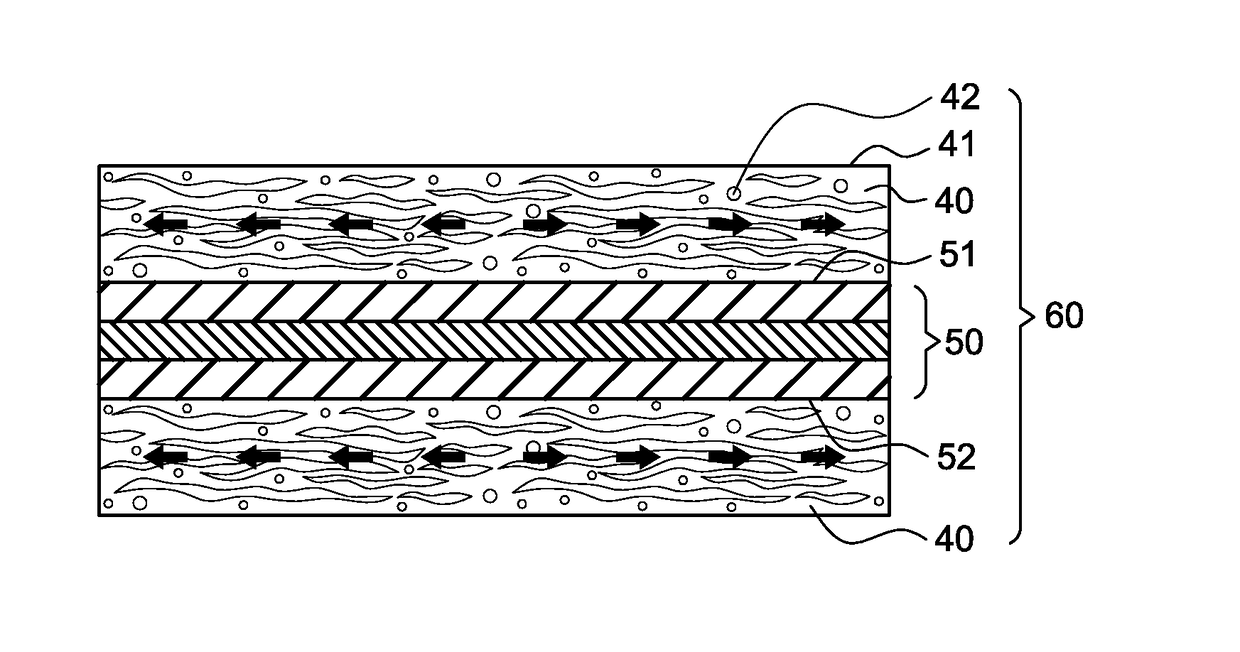
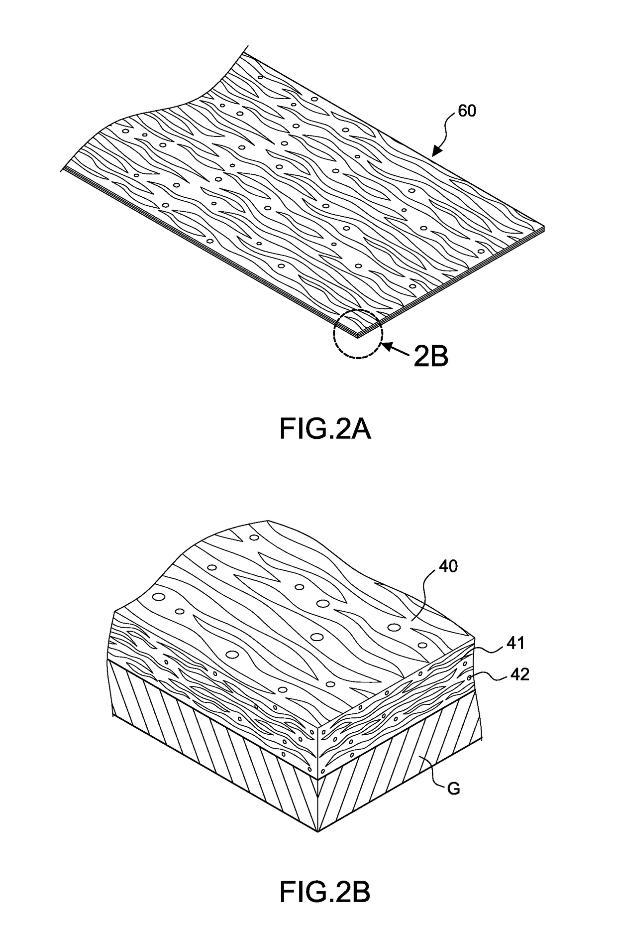
[0024]Referring to FIG. 1, a method for manufacturing a thermal balancing conductive coating includes steps as following.

[0025]Step a: providing gluey liquid 10 mixed by a compound substance and a first solution with a weight ratio of the first solution to the compound substance ranging from 1:0.6 to 1:1.4. The compound substance is selected from a group consisting of fluorocarbon resin, fluororesin, acrylic acid resin, polyurethane, polyurea resin, unsaturated polyester, silicon resin, and mixtures thereof. In this embodiment, the first solution is selected from a group consisting of thinner, ethyl acetate, ethanol, alcohols, ketones, esters, distilled water, and mixtures thereof.

[0026]Step b: providing a filler material 20 mixed by a filler substance and a second solution with a weight ratio of the compound substance to the filler substance ranging from 1:0.1 to 1:0.6 and a weight ratio of the second solution to the filler substance ranging from 1:0.3 to 1:0.8. The filler substanc...


PUM

PropertyMeasurementUnit
thicknessaaaaaaaaaa
thicknessaaaaaaaaaa
weight ratioaaaaaaaaaa

Abstract

A manufacturing method for a thermal balancing conductive coating includes steps as: a) providing gluey liquid mixed by a first solution and a compound substance with a weight ratio ranging from 1:0.6 to 1:1.4; the compound substance is selected from a group consisting of fluorocarbon resin, fluororesin, acrylic acid resin, polyurethane, polyurea resin, unsaturated polyester, silicon resin, and mixtures thereof; b) providing a filler material mixed by a second solution and a filler substance with a weight ratio ranging from 1:0.1 to 1:0.6 and another weight ratio of the compound substance to the filler substance from 1:0.3 to 1:0.8; the filler substance includes a main ingredient selected from a group consisting of graphite, graphene platelets, graphene, graphite fiber, graphene fiber, BN, mica, and mixtures thereof; c)mixing the gluey liquid and the filler material to produce a thermal balancing conductive material, so as to form a thermal balancing conductive coating.

Description

BACKGROUND OF THE INVENTION1. Field of the Invention[0001]The invention relates to a thermal balancing conductive compound piece and a manufacturing method thereof, particularly to a method that mixes a compound substance with a filler substance and produces a thermal balancing conductive coating with stain resistance and heat conduction.2. Description of the Related Art[0002]Currently common elements for heat dissipation in the markets are expensive and are not suitable for light and handy products. Therefore, a coating method for heat dissipation is developed for applications. However, the existing coating materials for heat dissipation have flaws of intolerance of weatherability and low temperature, and less resistance to stains and chemicals. The dissipation efficiency of the product is decreased due to these defects. On the other hand, the existing filler substance for manufacturing the coating materials cannot dissipate the heat very well because it does not contain ingredient...

Claims


Application Information

Patent Timeline
Patent Type & Authority Applications(United States)
IPC IPC(8): C09D5/26B32B15/082B32B15/095C09D201/04B32B15/20C09K5/10C09D7/12B05D1/00B32B15/09
CPCB32B15/082B32B15/095B32B15/09B32B15/20C09K5/10C09D7/1216B05D1/00B05D2202/00B32B2307/302B32B2457/00C08K3/04C09D5/26C09D201/04C09D7/61C09D5/00C09D5/24
Inventor CHEN, YU-CHIACHOU, CHING-I
Owner WHA YUEB TECH
Learn More