
Device for manipulating a tarpaulin

a technology for manipulating devices and tarpaulins, which is applied in the field of tarpaulins, can solve the problems of substantial risk, unnecessary wastage, and portion of the load being blown out of the open top container, and achieves the effects of convenient removal from the device, efficient resistance to these loads, and strong structur

Inactive Publication Date: 2008-11-27
ROYER REAL
View PDF9 Cites 31 Cited by
  • Summary
  • Abstract
  • Description
  • Claims
  • Application Information

AI Technical Summary

Benefits of technology

[0015]The proposed device is advantageous as it provides for a relatively smooth path along which the guiding component may be moved. Therefore, the device is conceived so as to facilitate the operation thereof and to minimize frictional forces that may occur between different components of the device. In turn, this ensures that the device is more reliable in operation and that the device may be used using a relatively small amount of material while remaining reliable.
[0016]Additionally, the device is conceived such that the guiding component is typically spaced apart by relatively a small distance from the aperture peripheral edge. Therefore, even if the aperture peripheral edge becomes damaged, which often occurs in top loaded containers, the device may continue to operate relatively smoothly.
[0017]The device is relatively easily operable by an intended user thereof using relatively simple and ergonomic steps.
[0019]In some embodiments of the invention, the tarpaulin mounting component may be relatively easily removed from the device so as to be exchanged with another elongated guiding component having different dimensions or different mechanical properties. This allows, for example, to accommodate loads having various shapes in the container. Advantageously, the tarpaulin mounting component used with the device may also be shaped so as to provide a relatively aerodynamic profile on the top of the container.
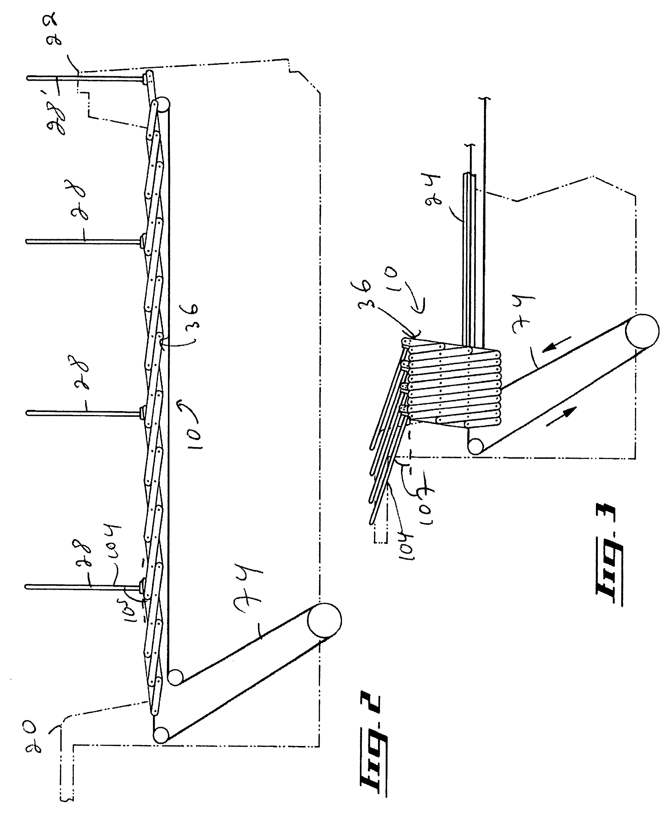
[0020]In some embodiments of the invention, the device is configured such that the tarpaulin mounting component pivots away from the top aperture when in the retracted configuration. In these embodiments, the interior of the container is therefore more easily accessible than in embodiments of the invention in which the tarpaulin mounting component would be simply slid towards the proximal end of the device.
[0021]Typically, many substantially longitudinally spaced apart tarpaulin mounting components are provided. In some embodiments, the tarpaulin mounting components are mechanically coupled to each other by a coupling system so as to be all movable when one of the tarpaulin mounting component is moved. Therefore, the coupling system is typically the portion of the system that bears most of the mechanical loads resulting from the movements of the tarpaulins, as opposed to many prior art systems in which tarpaulin mounting components or the tarpaulin bear these loads. Therefore, the coupling system may be engineered so as to efficiently resist to these loads. For example, an accordion-type system of hinged levers may be used, which provides for a relatively strong structure at relatively low cost and relatively low weight.

Problems solved by technology

During transportation in these so-called open top containers, there exists a substantial risk that a portion of the load may be blown out of the open top container by various physical phenomena such as vibration, aerodynamically created vacuum, wind or the like.
If some of the load is accidentally blown out of the container it may potentially not only cause unnecessary wastage of the transported goods but may also create a dangerous situation.
For example, when the open-top container is attached to a truck cabin, some of the load accidentally blown out of the container may contaminate the road or highway as it whirls around thus causing dangerous ground road conditions.
It may also be blown directly towards the windshield of following vehicles creating a potentially disastrous situation.
However, these devices are typically relatively complex.
In addition, they often require that an intended user of the device climb onto the container onto which the tarpaulin retracting and extending device is positioned.
This causes risks of injury to the intended user of these devices as the intended user may then fall from the container.
In addition, these devices often require that the intended user perform movements in non-ergonomic positions, which may also lead to injuries.
It often occurs that this top edge is damaged while the container is loaded.
In these cases, the movement of the bows is not smooth, which may lead to problems in moving the tarpaulin between the retracted and operative configurations.
In some cases, the bow may even drop off the edge of the container or the tarpaulin moving system may become damaged.
Another disadvantage of these systems resides in that typically, the tarpaulin is not completely retracted from the top aperture when in the retracted configuration, which restricts access to the container.
Yet another disadvantage of these systems resides in the bows are typically not linked to each other and are instead moved either by the tarpaulin as it is extended and retracted, or by the bows abutting against each other.
This results in the creation of relatively large forces in the tarpaulin moving system, which requires that the whole system be built relatively robustly, with all the cost and weight disadvantages associated to a robust construction.

Method used


Image

  • Device for manipulating a tarpaulin
  • Device for manipulating a tarpaulin
  • Device for manipulating a tarpaulin

Examples


Embodiment Construction

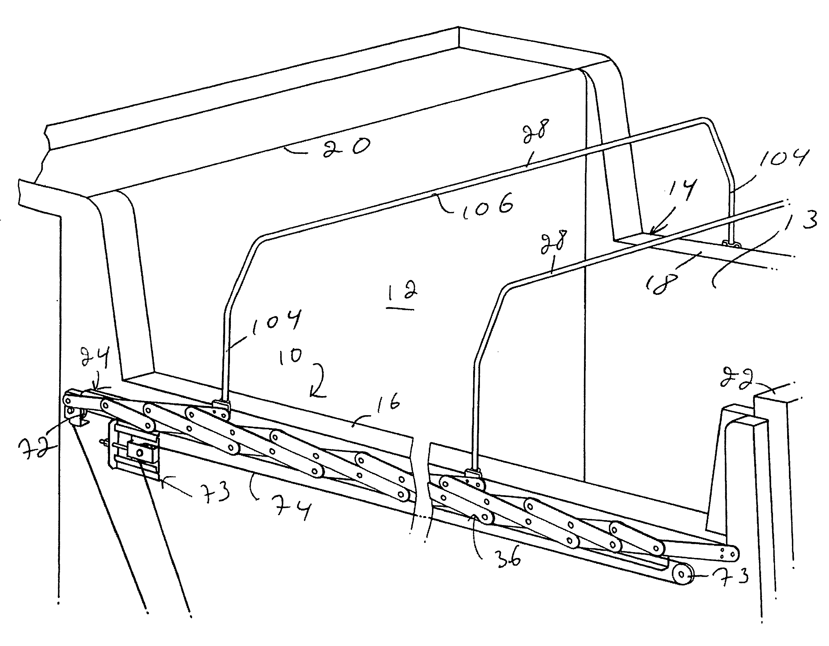
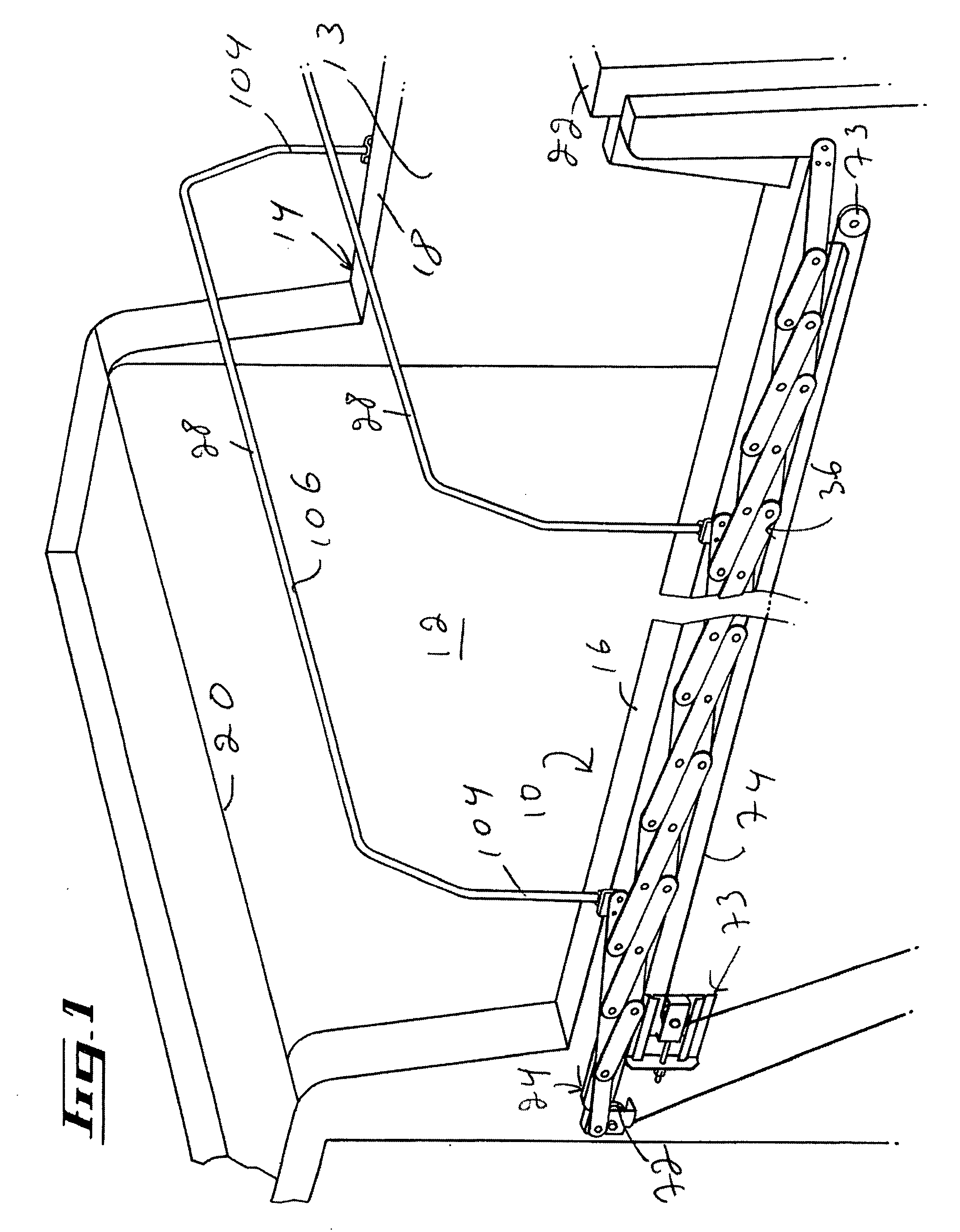
[0032]FIG. 1 illustrates a device 10 for manipulating a tarpaulin (now shown in the drawings) so as to selectively cover and uncover a top aperture 12 of a container 13. Although, in the drawings, the container 13 is a container of a dump truck, it is within the scope of the invention to use the device 10 with any other suitable container. Also, the term container should be interpreted as being a relatively generic term describing any assembly having a peripheral wall defining a top aperture to which one would like to have access. For example, the container could be a shed.

[0033]The top aperture 12 defines an aperture peripheral edge 14. The aperture peripheral edge 14 includes two substantially opposed longitudinal segments 16 and 18 and two lateral segments 20 and 22 extending between the longitudinal segments 16 and 18 substantially opposed to each other. Although the top aperture 12 has an aperture peripheral edge 14 having a substantially rectangular configuration in the drawin...


PUM


Abstract

A device for manipulating a tarpaulin so as to selectively cover and uncover a top aperture of a container. The top aperture defines an aperture peripheral edge, the aperture peripheral edge including two substantially opposed substantially longitudinal segments. The tarpaulin is configurable between an extended configuration and a retracted configuration. In the extended configuration, the tarpaulin substantially covers the top aperture. In the retracted configuration, the tarpaulin is substantially retracted from the top aperture. The device includes an elongated guiding component defining a guiding component longitudinal axis. The guiding component is securable to the container so as to extend at least partially along at least one of the longitudinal segments. A tarpaulin mounting component is usable for attaching the tarpaulin thereto. A link, mechanically coupled to the guiding component, is longitudinally movable therealong between a link proximal position and a link distal position. The tarpaulin mounting component is operatively coupled to the link in a manner such that when the link is in the link proximal position, and the tarpaulin is attached to the tarpaulin mounting component, the tarpaulin is in the retracted configuration. When the link is in the link distal position and the tarpaulin is attached to the tarpaulin mounting component, the tarpaulin is in the extended configuration.

Description

FIELD OF THE INVENTION[0001]The present invention relates generally to tarpaulins. More specifically, the present invention is concerned with a device for manipulating a tarpaulin.BACKGROUND OF THE INVENTION[0002]Vehicle cargo containers for transporting bulk material such as sawdust, gravel chip, cutter shavings and the like typically include open top boxes such as semi-trailers or the like defining side walls, a front wall, a rear wall and a floor. These open top containers are typically mechanically coupled to various types of vehicles such as cargo ships, railway carts and truck cabins for transporting goods between various locations.[0003]During transportation in these so-called open top containers, there exists a substantial risk that a portion of the load may be blown out of the open top container by various physical phenomena such as vibration, aerodynamically created vacuum, wind or the like. If some of the load is accidentally blown out of the container it may potentially ...

Claims


Application Information

Patent Timeline
Patent Type & Authority Applications(United States)
IPC IPC(8): B60P7/04
CPCB60J7/062
Inventor ROYER, REAL
Owner ROYER REAL
Learn More