
Gas Turbine Combustor

a technology of gas turbine combustor and combustor body, which is applied in the direction of machines/engines, burner control devices, lighting and heating apparatus, etc., can solve the problems of deterioration of explosion, etc., to secure the reliability and suppress the excessive temperature rise of the structure of the gas turbine combustor

Inactive Publication Date: 2017-10-05
MITSUBISHI HITACHIPOWER SYST LTD
View PDF0 Cites 7 Cited by
  • Summary
  • Abstract
  • Description
  • Claims
  • Application Information

AI Technical Summary

Benefits of technology

The present invention aims to prevent the temperature of a gas turbine combustor from rising too much, which could cause damage and reduce reliability. The invention provides a solution to suppress this temperature rise and ensure the continued reliability of the combustor.

Problems solved by technology

It is likely that explosion occurs because of, in particular, the hydrogen in the hydrogen content fuel in the gas turbine on the downstream side.
However, when the startup fuel is switched to the coal-derived syngas, flames generated by the respective fuels interfere with each other and the temperature of a structure of the gas turbine combustor excessively rises.
It is likely that the reliability of the gas turbine combustor is deteriorated.

Method used


Image

  • Gas Turbine Combustor
  • Gas Turbine Combustor
  • Gas Turbine Combustor

Examples


first embodiment

[0021](Configuration)

[0022]1. Gas Turbine Plant

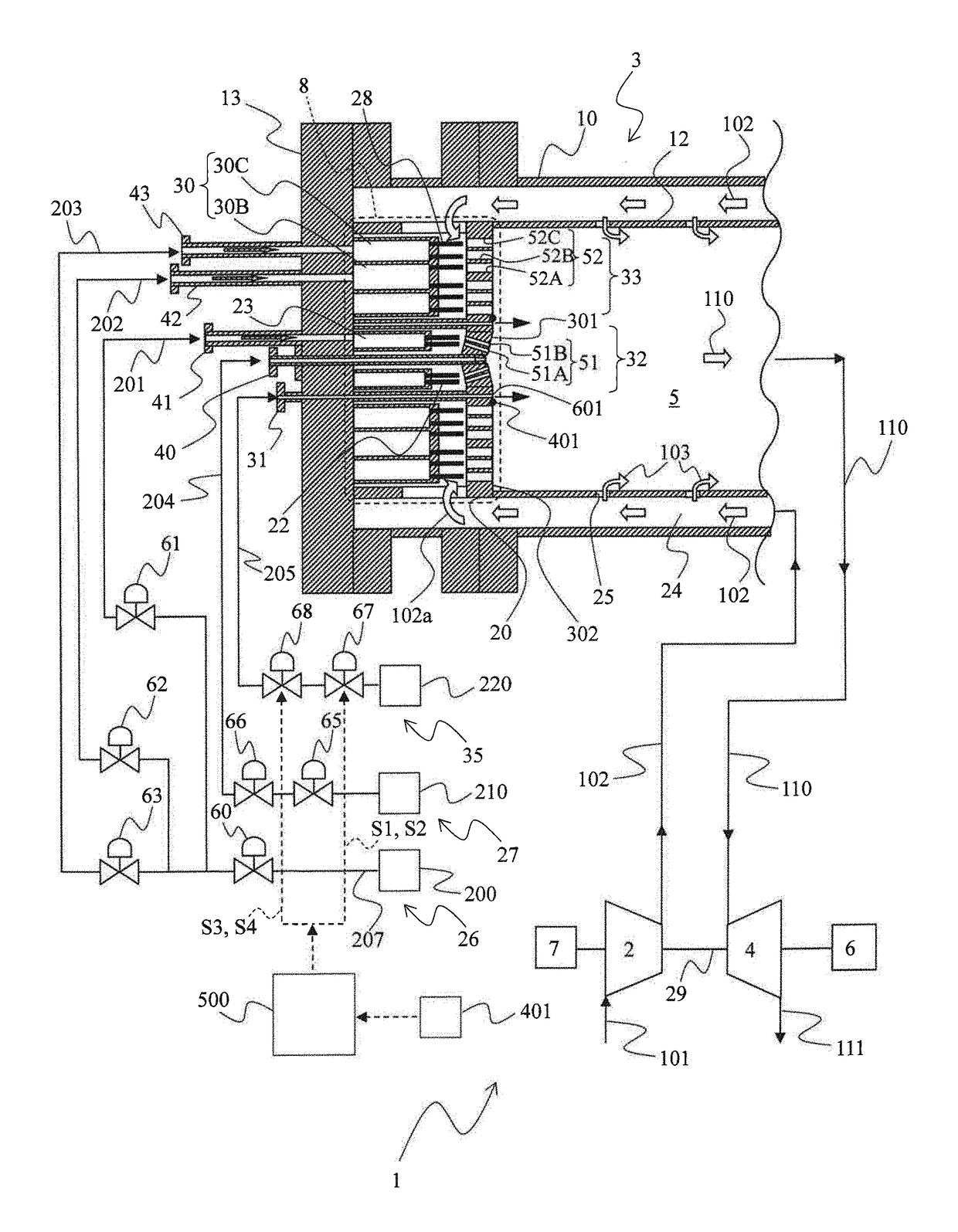
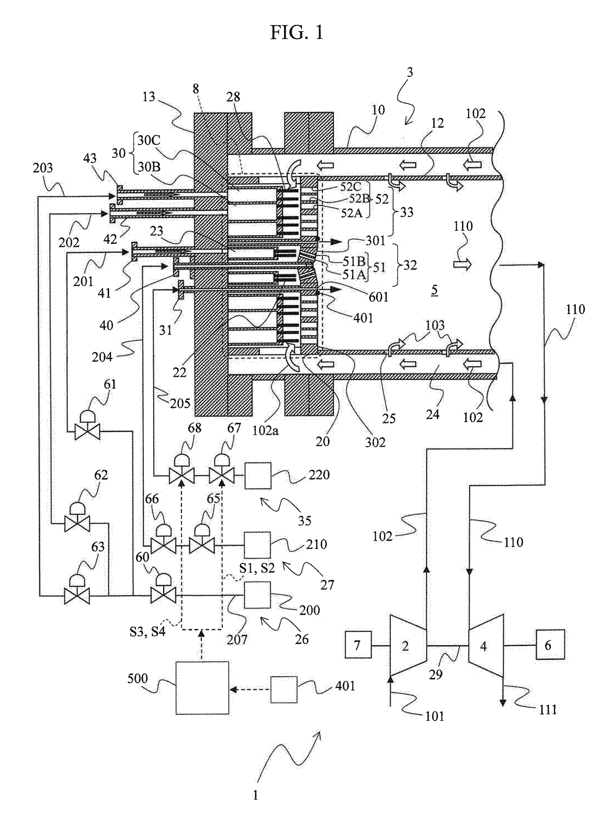
[0023]FIG. 1 is a diagram representing a configuration example of a gas turbine plant applied with a gas turbine combustor (hereinafter, combustor) according to this embodiment. As shown in FIG. 1, a gas turbine plant 1 includes a compressor (an air compressor) 2, a combustor 3, a turbine 4, a power generator 6, and a startup motor 7.

[0024]The compressor 2 is started up by the startup motor 7, compresses air 101 sucked from the atmosphere via an inlet (not shown in the figure) to generate high-pressure compressed air 102, and supplies the compressed air 102 to the combustor 3. The combustor 3 mixes the compressed air 102 supplied from the compressor 2 with fuel supplied from a fuel supplying system 26 (explained below) and burns the compressed air 102 and the fuel, generates high-temperature combustion gas 110, and supplies the combustion gas 110 to the turbine 4. The combustion gas 110 supplied from the combustor 3 expands, whereby the...

second embodiment

[0078](Configuration)

[0079]FIG. 9 is a diagram representing a configuration example of a gas turbine plant applied with a combustor according to this embodiment. In FIG. 9, portions equivalent to the portions in the first embodiment are denoted by the same reference numerals and signs and explanation of the portions is omitted as appropriate.

[0080]This embodiment is different from the first embodiment in that the cooling system 35 further includes a cooling pipeline 206, a cooling nozzle 34, a thermocouple 402, and a cooling hole 602. Otherwise, this embodiment is the same as the first embodiment.

[0081]As shown in FIG. 9, the cooling pipeline 206 branches from the cooling pipeline 205 and connects the coolant supply source 220 and the cooling nozzle 34. The cooling nozzle 34 is connected to the cooling hole 602. Coolant guided from the coolant supply source 220 to the cooling nozzle 34 through the cooling pipeline 206 is injected into the combustion chamber 5 via the cooling hole 60...


PUM


Abstract

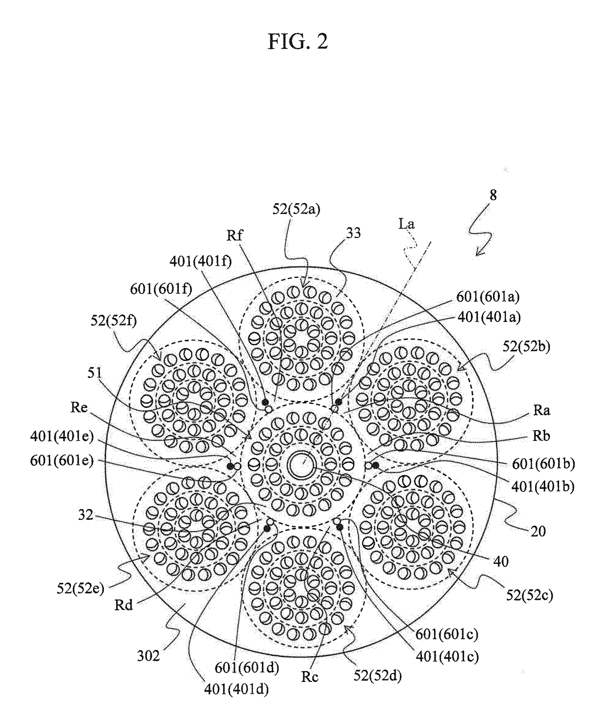
In a gas turbine combustor 3 of the present invention, an air hole plate 20 includes a center air hole group 51 configured from a plurality of air holes 51A and 51B and a plurality of outer circumferential air hole groups 52 configured from a plurality of air holes 52A, 52B, and 52C and formed to surround the center air hole group 51. The gas turbine combustor 3 includes a hole part 601 and a temperature sensor 401 provided on the air hole plate 20 to be located in a region surrounded by two outer circumferential air hole groups 52 adjacent to each other and the center air hole group 51, a supply source 220 of coolant, a cooling pipeline 205 that connects the hole part 601 and the supply source 220, valves 67 and 68 provided in the cooling pipeline 205, and a control system 500 that drives the valves 67 and 68 on the basis of a measured value of the temperature sensor 401.

Description

BACKGROUND OF THE INVENTIONField of the Invention[0001]The present invention relates to a gas turbine combustor.Description of the Related Art[0002]In recent years, from the viewpoint of prevention of global warming, effective use of natural resources, there are increasing tendencies of using, as fuel of a gas turbine combustor, gas containing hydrogen such as a coke oven gas by-produced in iron works and off-gas by-produced in oil refineries. The fuel of this type (hereinafter, hydrogen content fuel) has less emissions of carbon dioxide (CO2), which causes the global warming, in combustion and is effective for prevention of the global warming. In an integrated coal gasification combined cycle plant (IGCC plant) that gasifies coal, which is an abundant resource, and generates power, a system (carbon capture & storage: CCS) that captures and stores carbon in hydrogen content fuel (coal-derived syngas) supplied to a gas turbine combustor is provided to further reduce the emission of C...

Claims


Application Information

Patent Timeline
Patent Type & Authority Applications(United States)
IPC IPC(8): F23R3/00
CPCF23R3/002F23R3/283F23N5/107F23N5/242F23R3/34F23R3/36F23C2900/99011F23D2208/10F23D2214/00F23R2900/00005Y02E20/16Y02E20/18F23N2241/20F02C6/00F23R3/06F23R3/42F23R2900/03045F05D2240/35
Inventor ASAI, TOMOHIROHAYASHI, AKINORIAKIYAMA, YASUHIRO
Owner MITSUBISHI HITACHIPOWER SYST LTD
Learn More