
Condenser for a steam power plant

a steam power plant and condenser technology, which is applied in steam engine plants, corrosion prevention, lighting and heating apparatus, etc., can solve the problems of steam present in steam turbine condensing, unplanned shutdown states of unforeseeable duration, and power plant operators having to put their power plants into more frequent shutdown states, etc., to reduce evaporation in the hotwell, simple and inexpensive manner, and easy operation

Inactive Publication Date: 2017-09-28
SIEMENS AG
View PDF11 Cites 0 Cited by
  • Summary
  • Abstract
  • Description
  • Claims
  • Application Information

AI Technical Summary

Benefits of technology

The invention provides a way to retrofit existing condener plants in a simple and inexpensive way. It uses a large number of floating bodies that are automatically adapted to the current condenser geometry, eliminating the need for individual parts. The invention reduces evaporation in the hotwell, resulting in lower drying costs and minimizing damage to the turbine. It also reduces the risk of corrosion and damage to the turbine. Overall, the invention provides a cost-effective way to improve efficiency and reduce risks in existing condener plants.

Problems solved by technology

The current market requirements lead to the power plant operators having to put their power plants into more frequent, unscheduled shutdown states of unforeseeable duration.
This means, however, that after the shutting down of a steam turbine the steam which is present in the steam turbine condenses as soon as the temperature falls below the dew point.
The combination with the water which is available from the condenser, with the oxygen which is provided by means of the vacuum breaker and the shaft bushing, and with the metal, leads to a possible occurrence of corrosion.
Therefore, in the case of a stationary steam turboset the risk of stagnant-condition corrosion inside the turbine casing, valve housings and condensers may exist as soon as the relative air moisture of the ambient air inside the respective components exceeds a limit value or the surface temperature of the metal parts inside the turbine and valve housings and also condensers cools down in such a way that the metal parts can fall below the dew point temperature.
In particular, the final stages of low-pressure turbine sections and the condenser are at risk of corrosion since even during operation their temperatures lie close to the dew point or already lie below it.
This, however, results in the evaporation leading to an increase of the moisture in the condenser and in the low-pressure turbine section adjoining it.

Method used


Image

  • Condenser for a steam power plant
  • Condenser for a steam power plant

Examples


Embodiment Construction

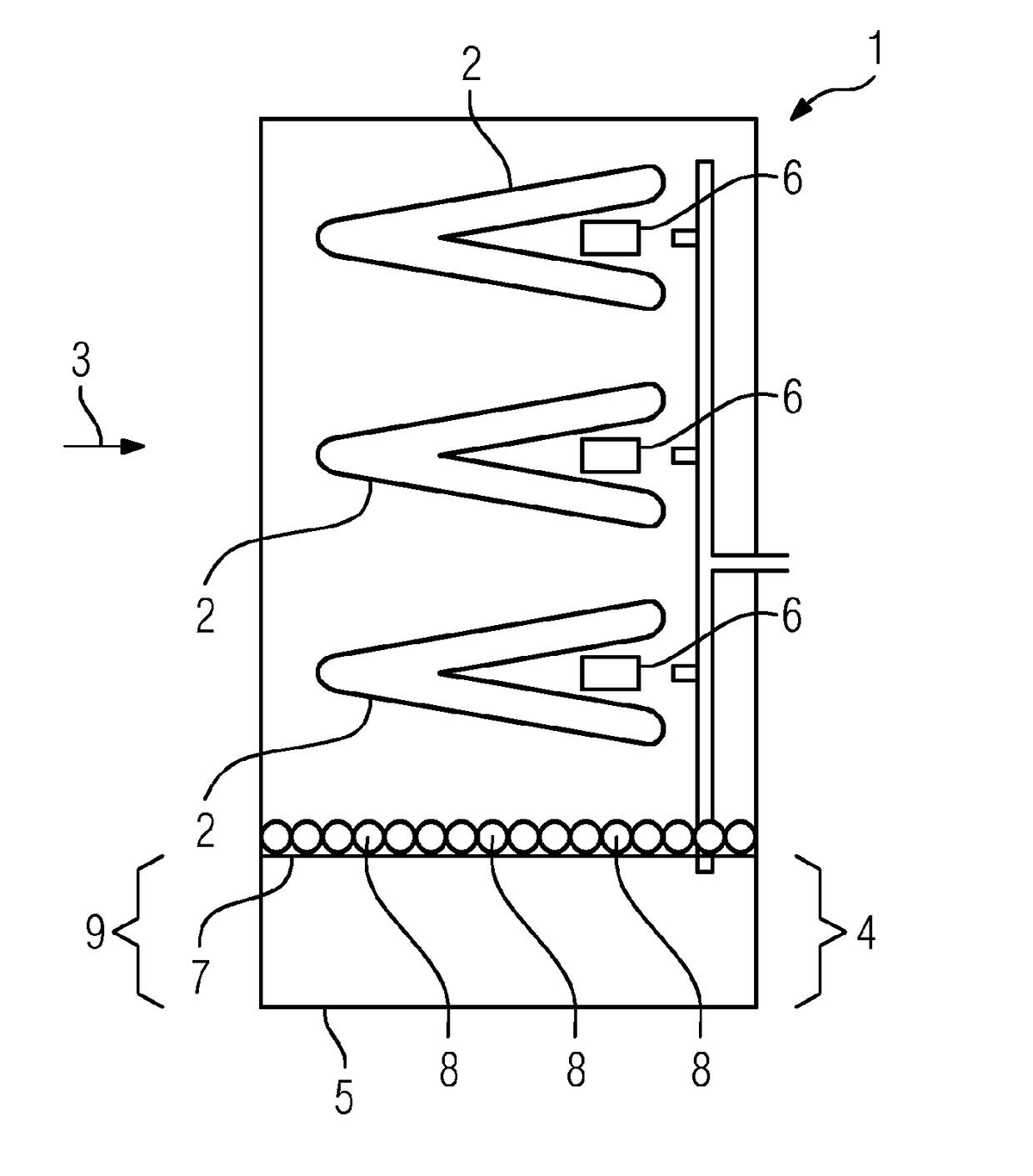
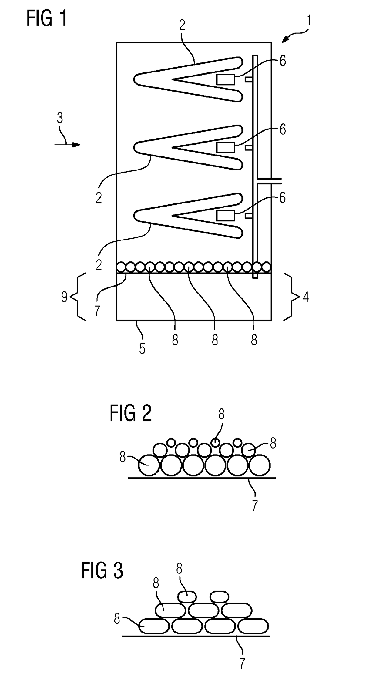
[0030]FIG. 1 shows a cross-sectional view of a condenser 1 for a steam power plant, which is not shown in more detail. The condenser 1 comprises a plurality of tube bundles 2 which are arranged in a steam flow 3. Cooled water flows through the tube bundles 2, which leads to the water vapor from the steam flow 3 condensing on the surfaces of the tube bundles 2 and, as water, coming into a region 4 in which the water collects to form a condensate 5. The steam flow 3 is fluidically connected to a low-pressure turbine section. Furthermore, the condenser 1 comprises air coolers 6 which are arranged in the region of the tube bundles 2.

[0031]The condensate 5 forms a condensate surface 7.

[0032]According to the invention, floating bodies 8 are arranged on this condensate surface 7. In FIG. 1, for reasons of clarity, only three floating bodies 8 are provided with the designation 8. These floating bodies 8 wet the condensate surface 7 and consequently reduce the contact area of the condensate ...


PUM


Abstract

A method for operating a condenser, wherein the condenser is designed for condensing water vapor to form water and during operation a condensate having water accumulates in the condenser, wherein on the condensate surface a plurality of floating bodies are arranged on the condensate, wherein the floating bodies float on the condensate, wherein a large number of floating bodies are used in such a way that the condensate surface is covered, wherein the floating bodies are of spherical and / or sphere-like design, and wherein floating bodies with different sizes are used.

Description

CROSS REFERENCE TO RELATED APPLICATIONS[0001]This application is the US National Stage of International Application No. PCT / EP2015 / 069010 filed Aug. 19, 2015, and claims the benefit thereof. The International Application claims the benefit of European Application No. EP14181545 filed Aug. 20, 2014. All of the applications are incorporated by reference herein in their entirety.FIELD OF INVENTION[0002]The invention relates to a method for operating a condenser.BACKGROUND OF INVENTION[0003]Modern power plants as a rule comprise a gas and steam turbine plant and electric generators which are designed for generating electric energy. The torque-transmitting drive for the electric generators is carried out via the shafts of the gas turbine and / or steam turbine.[0004]During operation, steam, which is produced in a steam generator, flows to a high-pressure turbine section and from there to a reheater in which the steam is brought up to a certain temperature. After the reheating, the steam fl...

Claims


Application Information

Patent Timeline
Patent Type & Authority Applications(United States)
IPC IPC(8): F28B9/00F28F19/00F28B9/08
CPCF28B9/00F01K11/00F28F19/002F28B9/08F01K9/00
Inventor BRUNE, KAIBRUSSK, STEFANCOX, NIGEL-PHILIPDREIER, DANIELGABL-ZIMMEK, TOBIASGHICOV, ANDREIHU, MARIEKOEBE, MARIOLANGE, MARCPOTT, TERESARIEMANN, STEFANULMA, ANDREASVELTMANN, DAVIDZIMMER, GERTA
Owner SIEMENS AG
Learn More