
Solenoid valve assembly of variable damping force damper and method of assembling the same

a technology of variable damping force and valve assembly, which is applied in the direction of valve operating means/release devices, shock absorbers, mechanical devices, etc., can solve the problems of deteriorating the affecting both driving comfort and handling stability of the vehicle, and deteriorating operability, so as to achieve simple and inexpensive manner

Inactive Publication Date: 2009-08-13
HL MANDO CORP
View PDF36 Cites 13 Cited by
  • Summary
  • Abstract
  • Description
  • Claims
  • Application Information

AI Technical Summary

Benefits of technology

[0009]One embodiment provides a solenoid valve assembly of a variable damping force damper, which is configured to permit a bobbin housing to be fastened to a valve housing in a simple and inexpensive manner, with orientation of a power line secured, after the valve housing is primarily secured to an embedded assembly, and a method of assembling the same.
[0015]According to one embodiment, the solenoid valve assembly allows orientation of a power line to be easily secured when securing the solenoid valve assembly to a damper, and allows partial assembly of the solenoid valve assembly to be very easily and simply carried out.

Problems solved by technology

A damping force of the damper affects both driving comfort and handling stability of the vehicle.
For example, a low damping force of the damper enhances driving comfort but deteriorates the handling stability of the vehicle.
However, this technique deteriorates operability and causes product failure or unfavorable operation, which requires reassembly operation, thereby deteriorating economic feasibility.
In this technique, however, the additional components cause a cost increase and a size increase of the solenoid valve, which results in an increase in weight thereof.

Method used


Image

  • Solenoid valve assembly of variable damping force damper and method of assembling the same
  • Solenoid valve assembly of variable damping force damper and method of assembling the same
  • Solenoid valve assembly of variable damping force damper and method of assembling the same

Examples


Embodiment Construction

[0019]Some embodiments will now be described in detail with reference to the accompanying drawings. The embodiments are given by way of illustration and example for full understanding by those skilled in the art. Hence, the present disclosure and claims that follow are not limited to these embodiments and can be realized in various forms. Further, for convenience of description, width, length, and thickness of components are not drawn to scale in the drawings. Like components are indicated by like reference numerals throughout the specification.

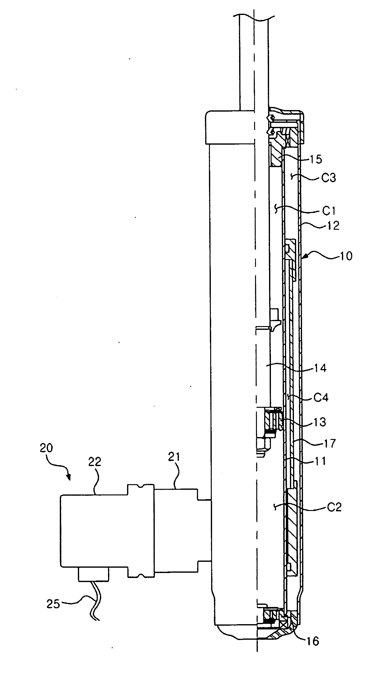
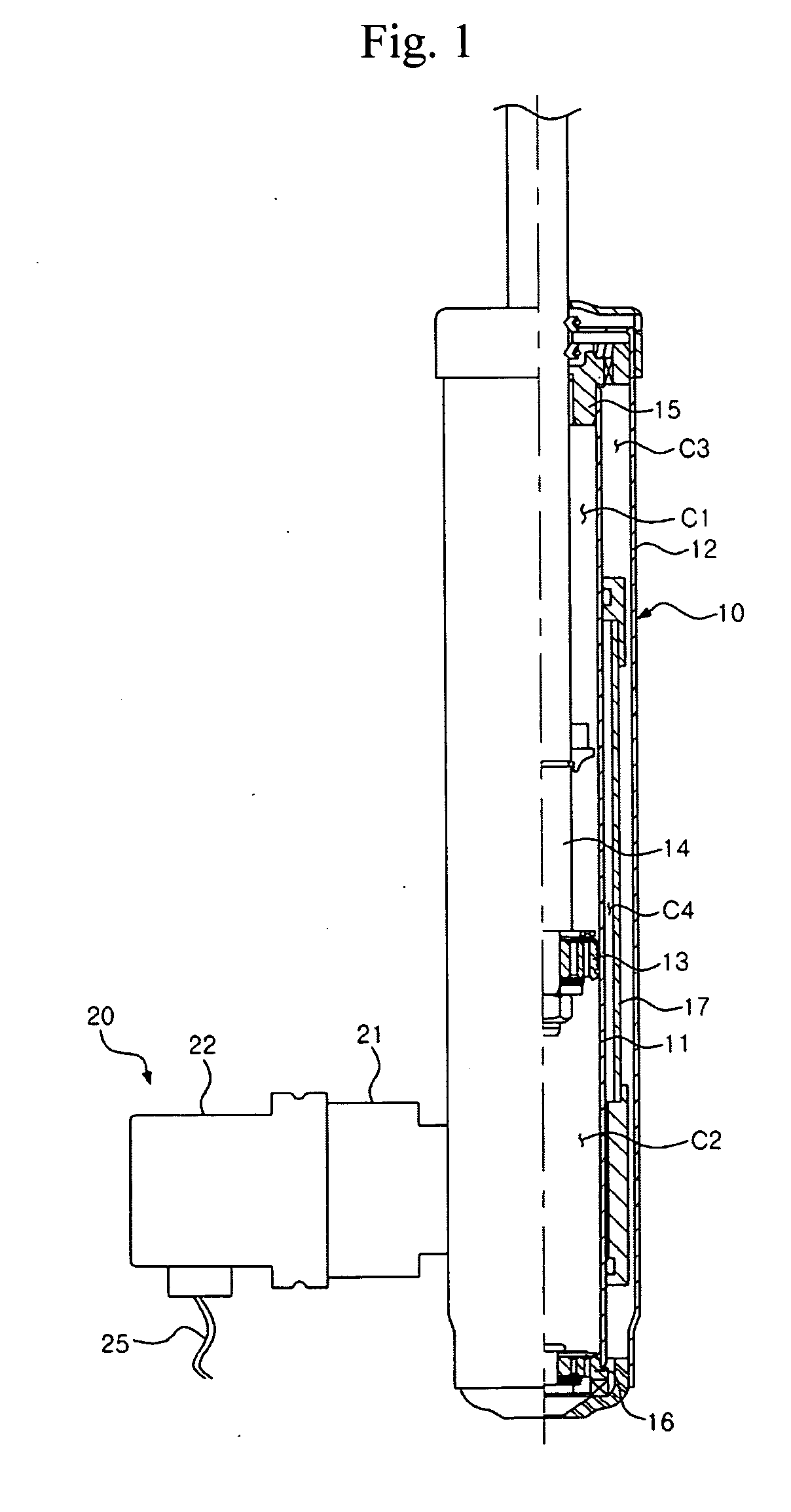
[0020]Referring to FIG. 1, which is a partial cross-sectional view of a variable damping force damper including a solenoid valve assembly according to one embodiment, the variable damping force damper includes a damper 10, and a solenoid valve assembly 20 secured to one side of the damper 10 and used for variable control of a damping force. The solenoid valve assembly 20 has an inlet and an outlet connected to high and low pressure sides of t...


PUM


Abstract

A solenoid valve assembly of a variable damping force damper and a method of assembling the same are disclosed. The method includes coupling a valve housing to one side of a damper, accommodating an embedded assembly within the valve housing, the embedded assembly including a variable fluid path component and a solenoid operator, disposing a bobbin housing such that an inner circumference of the bobbin housing partially overlaps an outer circumference of the valve housing, while adjusting orientation of a power line connected to a bobbin accommodated in the bobbin housing, and fastening the bobbin housing to the valve housing, with the orientation of the power line adjusted.

Description

BACKGROUND[0001]1. Technical Field[0002]The present disclosure relates to a solenoid valve assembly of a variable damping force damper and a method of assembling the same, and, more particularly, to technology capable of enhancing ease of assembly of a variable damping force damper.[0003]2. Description of the Related Art[0004]Generally, a vehicle is provided with a damper (or shock absorber) for absorbing and releasing impact or vibration transmitted from a road or a part of the vehicle during driving. A damping force of the damper affects both driving comfort and handling stability of the vehicle. For example, a low damping force of the damper enhances driving comfort but deteriorates the handling stability of the vehicle. For this reason, in the case of turning, accelerating, braking or high speed driving of the vehicle, it is necessary to improve the handling stability of the vehicle by increasing the damping force to suppress variation in posture of a vehicle body.[0005]In recen...

Claims


Application Information

Patent Timeline
Patent Type & Authority Applications(United States)
IPC IPC(8): F16K31/02
CPCF16F9/325F16F9/34F16F9/32
Inventor PARK, KYU SHIK
Owner HL MANDO CORP
Learn More