
Structural assembly and method

a technology of structural assembly and materials, applied in the direction of sheet joining, material gluing, domestic articles, etc., can solve the problem of difficulty in effectively bonding dissimilar materials

Inactive Publication Date: 2017-09-28
SADR CHANGIZE
View PDF3 Cites 2 Cited by
  • Summary
  • Abstract
  • Description
  • Claims
  • Application Information

AI Technical Summary

Benefits of technology

The invention is an assembly of materials that includes two members that are mechanically interlocked. The first member is made of a first material that is less hard than the second material. The second member has an array of mechanical interlock members that are embedded in the first member. The assembly has a through thickness and is resistant to bending. The first member can be made of a polymer, aluminum, or stainless steel, and the second member can be made of aluminum, copper, or other metals. The assembly can be used as a foot support or an exterior body panel of an automobile. The mechanical interlock members can be hooks, prongs, or barbs. The first member can have a cell wall orientation that is predominant towards the second member. The assembly can also include a third member that acts as a flange. The first and second members can be made of different materials. The assembly can be used to provide a rigid body resistant to bending.

Problems solved by technology

In manufacturing it is sometimes difficult to bond dis-similar materials effectively, or there may be instances where it is desired to join similar materials but without glues, adhesives, bonding agents, curing, welding, or chemical reaction processes.

Method used


Image

  • Structural assembly and method
  • Structural assembly and method
  • Structural assembly and method

Examples


Embodiment Construction

[0068]The description that follows, and the embodiments described therein, are provided by way of illustration of an example, or examples, of particular embodiments incorporating one or more of the principles, aspects and features of the present invention. These examples are provided for the purposes of explanation, and not of limitation, of those principles, aspects and features of the invention. In the description, like parts are marked throughout the specification and the drawings with the same respective reference numerals. The drawings may be taken as being to scale, or generally proportionate, unless indicated otherwise. In the cross-sections, the relative thicknesses of the materials may typically not be to scale, with the thickness of cladding materials typically being substantially exaggerated for the purposes of explanation.

[0069]The scope of the invention herein is defined by the claims. Though the claims are supported by the description, they are not limited to any parti...


PUM

PropertyMeasurementUnit
Areaaaaaaaaaaa
Mechanical propertiesaaaaaaaaaa
Surfaceaaaaaaaaaa

Abstract

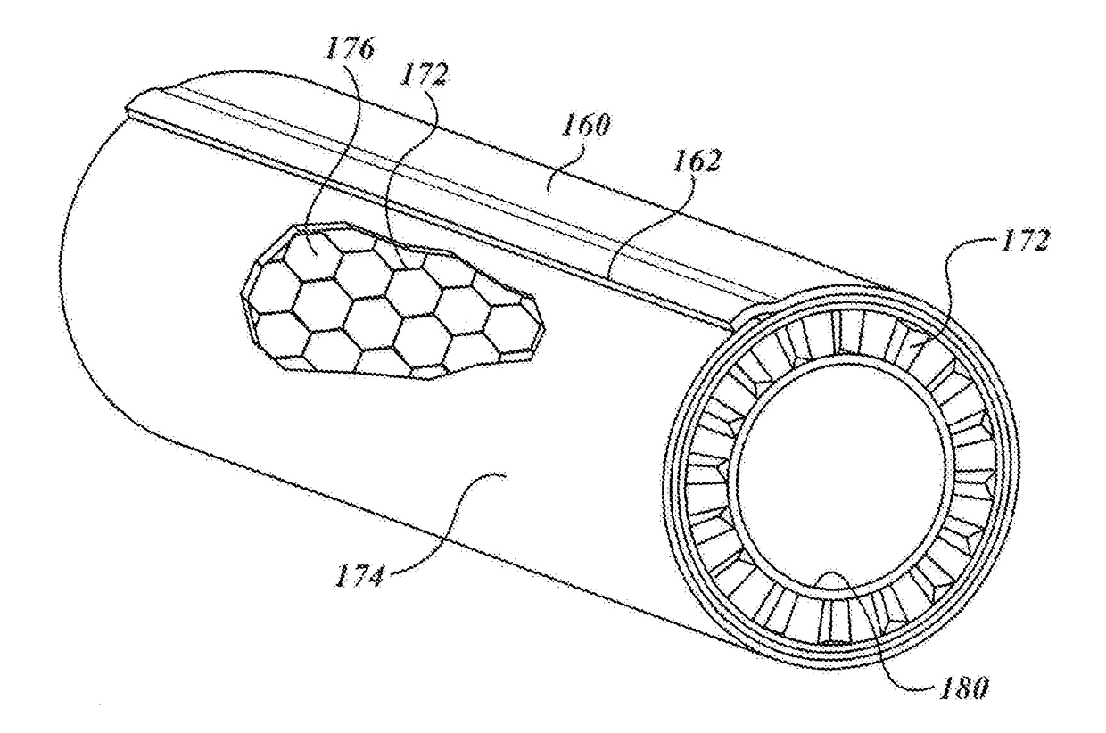
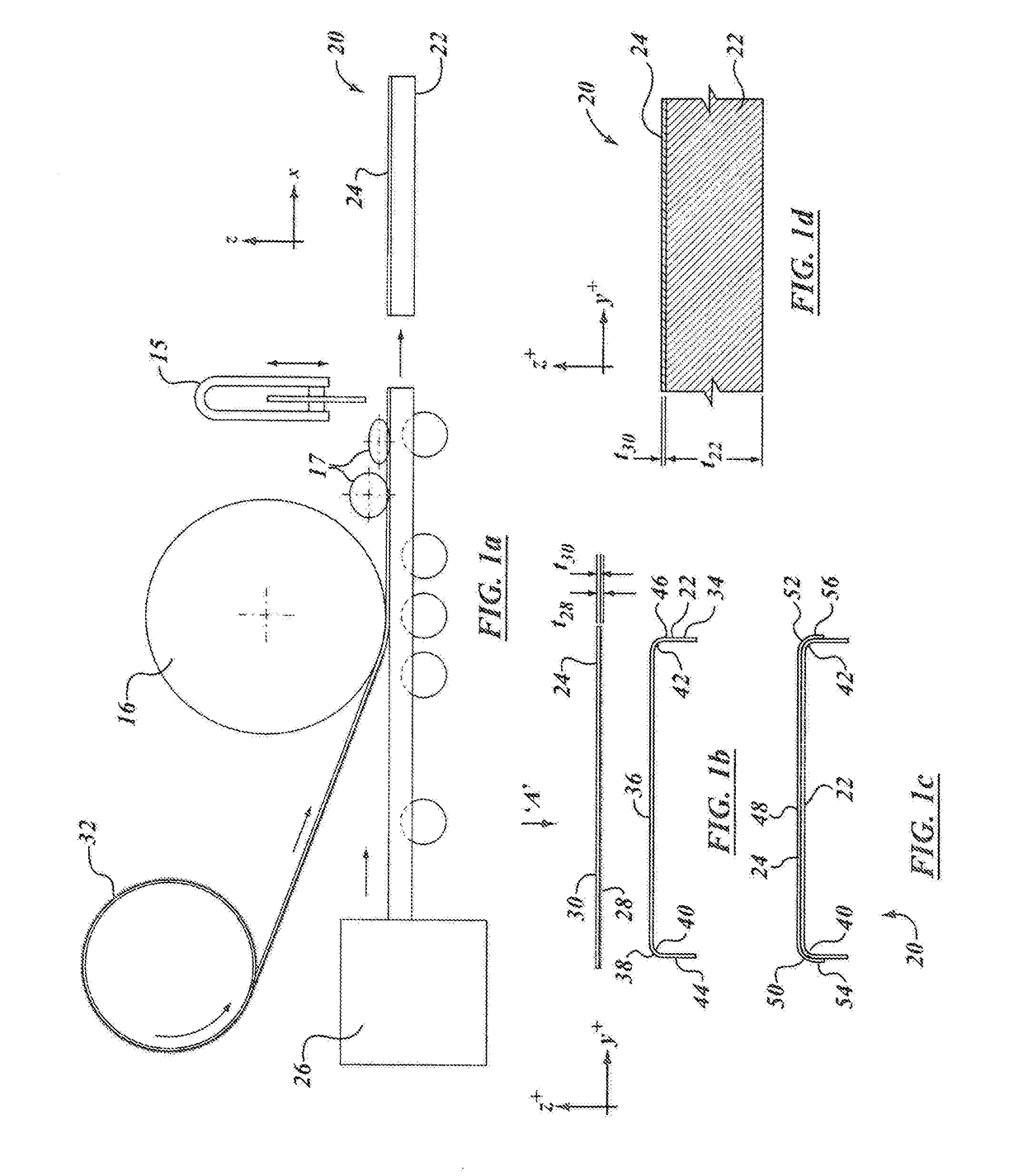
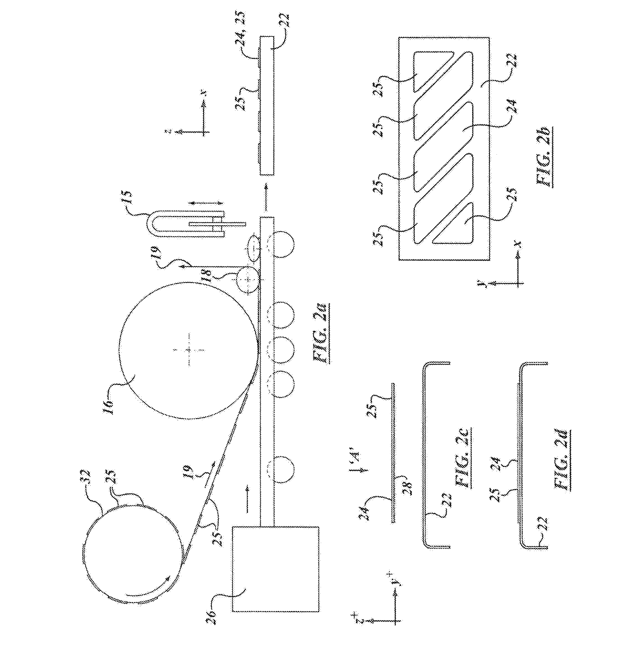
A structural assembly includes a first member defining a matrix material, and a second member defining a skin. The skin has a roughed surface of hooks or barbs. The second member is engaged to the first member to define a mechanically interlocked assembly. The assembly may include an open-cell matrix material in a glue-less connection. The assembly may include a chemical bond in addition to a mechanical bond. The assembly may include internal layers of pre-impregnated composite fiber and resin. The skin member may act as a jig for a green composite member. The skin member may be deformed in a press to present a non-planar surface for such other members as may be attached to it. Assemblies may be formed with mechanical interconnection in place of glue or adhesive connections. Assemblies may be formed to may light, thin-walled pipe, flasks, pressure vessels and so forth.

Description

[0001]This application claims the benefit of priority of U.S. Provisional Patent Application 61 / 979,702 filed Apr. 15, 2014, the specification and drawings thereof being incorporated by reference herein in their entirety.FIELD OF INVENTION[0002]This description relates to structures of mechanically connected materials and methods of manufacture pertaining to those structures.BACKGROUND OF THE INVENTION[0003]The joining of similar or dis-similar materials may involve dis-similar metals, dis-similar polymers, or dis-similar lignocellulosic materials, or a combination of those groups. In manufacturing it is sometimes difficult to bond dis-similar materials effectively, or there may be instances where it is desired to join similar materials but without glues, adhesives, bonding agents, curing, welding, or chemical reaction processes. It may also involve adhesive bonding welding, or gluing processes that may have significant curing times, or that may involve the off-gassing of chemicals ...

Claims


Application Information

Patent Timeline
IPC IPC(8): F16B17/00B29C70/08F16L9/17B29C70/84F16B5/01F16B11/00
CPCF16B17/008F16B5/01F16B11/006F16L9/17B29L2031/7156B29C70/088B29L2023/22B29L2031/608B29C70/84B29C70/86
Inventor SADR, CHANGIZE
Owner SADR CHANGIZE
Learn More