
3D printer systems and methods

a technology of 3d printers and printers, applied in the field of 3d printer systems and methods, can solve problems such as deformation of printed lines

Active Publication Date: 2017-09-21
GIFFORD KARL JOSEPH DODDS +2
View PDF3 Cites 27 Cited by
  • Summary
  • Abstract
  • Description
  • Claims
  • Application Information

AI Technical Summary

Benefits of technology

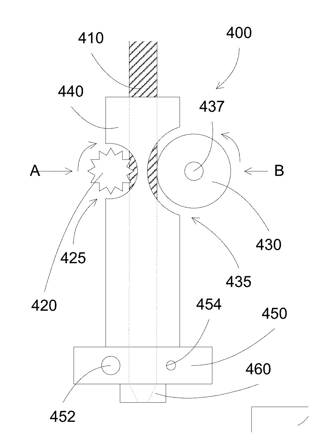
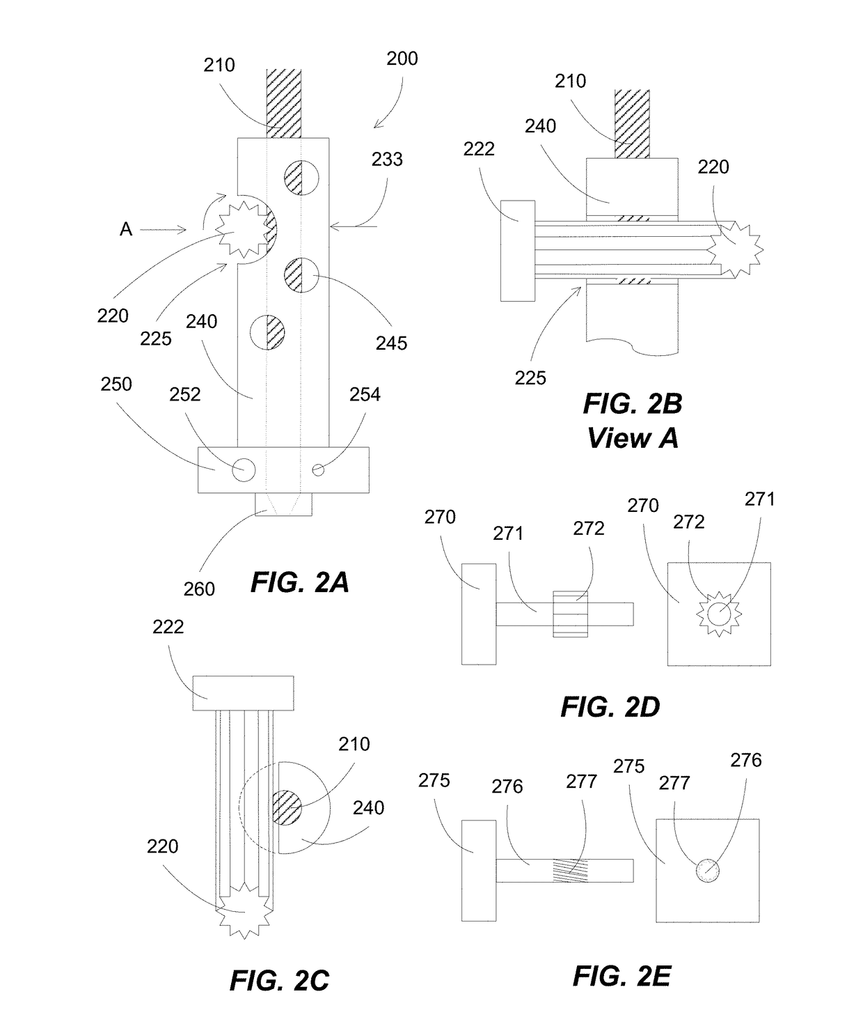
The present invention is a print head for a 3D printer that can print structures using a filament. The print head has two hobbed shafts that can rotate to drive the filament to a heated chamber. The print head includes a conduit with a channel for guiding the filament, and a low friction material, such as Teflon, to assist in the movements of the filament. The conduit has cut portions that expose a portion of the channel, through which shafts or gears can pass to contact the filament. This design allows for easy insertion of the filament and prevents filament accumulation. The technical effects of this invention include improved filament movement and efficient printing of structures.

Problems solved by technology

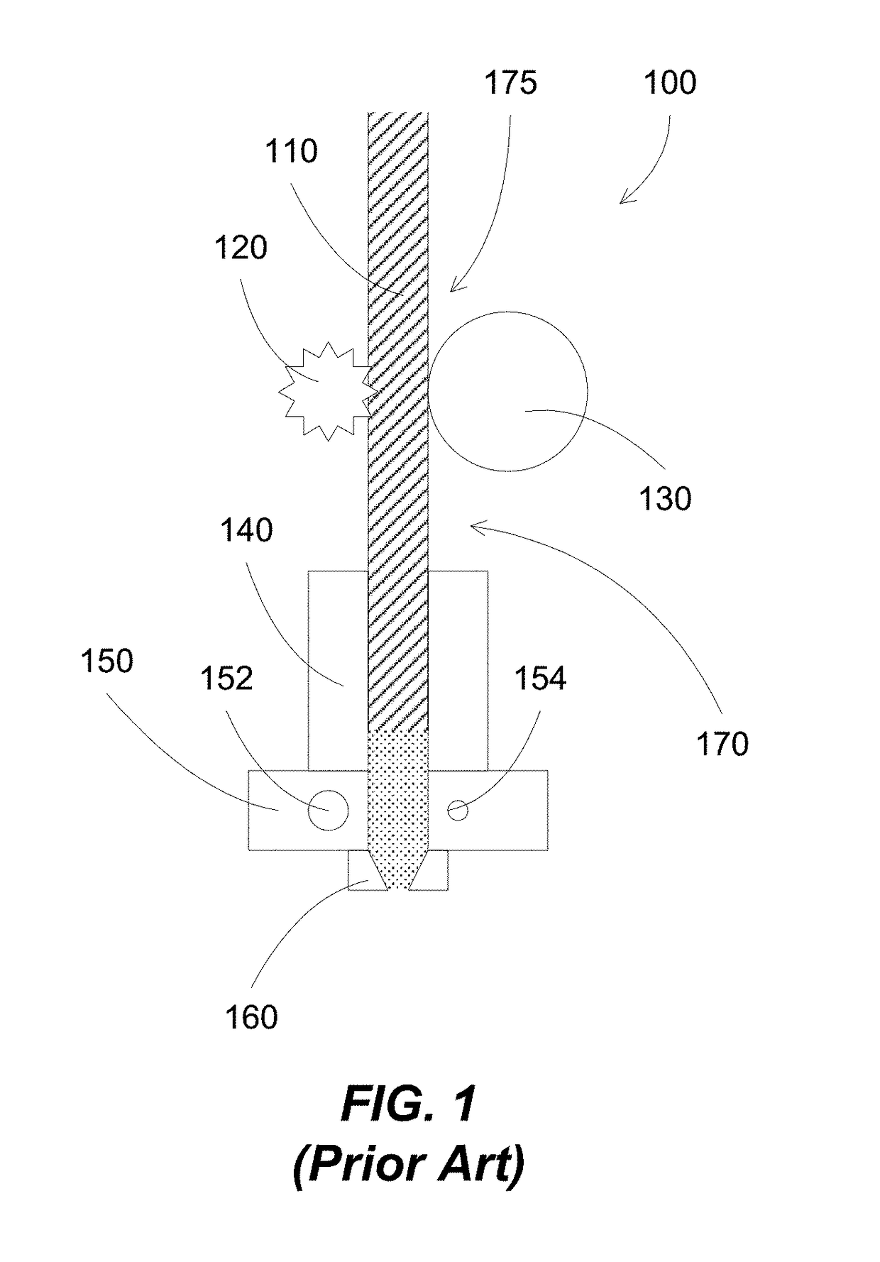
The melted filament can adhere to the walls of the heated printer head, resulting in a deformed printed lines.

Method used


Image

  • 3D printer systems and methods
  • 3D printer systems and methods
  • 3D printer systems and methods

Examples


Embodiment Construction

[0058]Additive manufacturing processes generally fabricate 3D objects by depositing layers by layers in patterns corresponding to the shape of the objects. At each layer, a print head can deposit building materials at locations corresponded to the pattern of the object for that layer.

[0059]3D printing processes can include inkjet printing, stereolithography and fused filament fabrication. In inkjet printing processes, liquid material are released from an inkjet print head, and solidified on the substrate surface, e.g., on the model being formed. In stereolithography processes, a UV light can crosslink layers of photopolymer. In fused filament fabrication processes, a continuous filament of thermoplastic can be softened or melted and then re-solidified on a previously deposited layer. Alternatively, paste-like materials can be used for printing, for example, through a pressure extrusion device such as a piton / cylinder.

[0060]Various polymers are used, including acrylonitrile butadiene...


PUM

PropertyMeasurementUnit
diameteraaaaaaaaaa
diameteraaaaaaaaaa
angleaaaaaaaaaa

Abstract

A print head comprising two shafts disposed in opposite sides of a filament to drive the filament to a heated chamber for delivering a molten material. The shafts are actively driven, for example, by two independent motors. The two shaft configuration of the print head can improve a control of the filament movement rate, especially for soft filament materials.

Description

[0001]The present application claims priority from U.S. Provisional Patent Application Ser. No. 62 / 310,816, filed on Mar. 21, 2016 entitled: “3D printer systems and methods” (HYREL009-PRO), which is incorporated herein by reference.BACKGROUND OF THE INVENTION[0002]3D printers can be used to build solid objects by printing layers by layers of building materials. The building materials can be in liquid or semi liquid form at the 3D printer head, for example, a solid material can be heated and then extruded from a 3D printer nozzle. The layers of building materials can be solidified on a substrate.[0003]3D printer systems can use a fused filament fabrication (FFF) process (sometimes called fused deposition modeling (FDM) process) in which a filament is moved, e.g., by a filament moving mechanism, toward a heated zone. The filament can be melted, and extruded on a platform to form a 3D object. The melted filament can adhere to the walls of the heated printer head, resulting in a deforme...

Claims


Application Information

Patent Timeline
Patent Type & Authority Applications(United States)
IPC IPC(8): B29C67/00B33Y30/00B33Y50/02B33Y10/00
CPCB29C67/0088B29C67/0055B33Y50/02B33Y30/00B33Y10/00B29C64/209B29C64/321B29C64/118
Inventor GIFFORD, KARL JOSEPH DODDSNGUYEN, TAI DUNGNGUYEN, TUE
Owner GIFFORD KARL JOSEPH DODDS
Learn More